


Data Highway Message Set
Chapter 8
832
Unless otherwise stated, values shown are in hexadecimal, and each block
shown represents one byte.
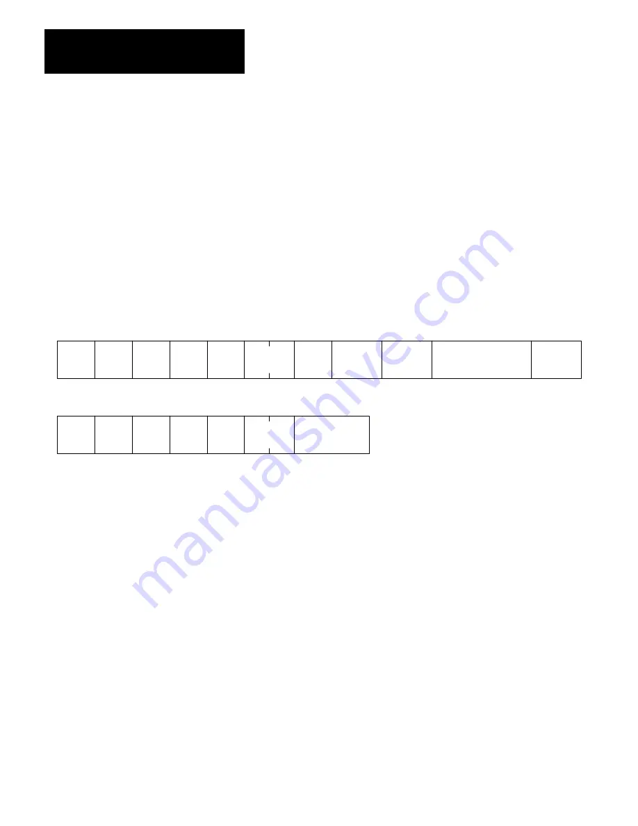
Read File
Use this command to read a file at the destination. Use the address
(L ADDR) field to specify a logical file address. In the first packet of a
transaction, the packet-offset value is 00. In subsequent packets of a
transaction, use the packet-offset field to specify the word (within the file)
at which the read starts for the packet. Use the total-transaction field to
specify the number of bytes to read in the total transaction. Use the SIZE
field to specify the number of bytes to read for the specific packet.
TNS
2 Bytes
CMD
0F
USER
NODE
LINK
STS
00
FNC
04
PACKET
OFFSET
TNS
2 Bytes
CMD
4F
USER
NODE
LINK
STS
00
Command Format:
SuccessReply Format:
TOTAL
TRANS
L ADDR
251 Bytes
SIZE
DATA
244 Bytes Max.
Unless otherwise stated, values shown are in hexadecimal, and each block
shown represents one byte.
Download Privilege
Use this command only as one step in the download procedure described
in “PLC-3 Upload/Download Procedures.” When the PLC-3 station
returns a success reply, your computer has the exclusive privilege to
download to the PLC-3 memory. This locks out all other stations in the
network from writing into the PLC-3 memory.