20
IDR-8
User Guide
Getting Started – Checking the Hardware
The
iDR-8
is supplied with its settings pre-configured so that you can turn it on and
immediately get audio passing through it. This can be useful when you are installing a unit
on site and need to carry out initial tests on the hardware before the custom configuration
software is loaded. This can be done without the need to connect your PC and run the iDR
System Manager software. When shipped, the
iDR-8
is loaded with the DEFAULT
configuration. The iDR software provided with the unit also includes this configuration file
so that you can load it again later if you want to restore the default settings.
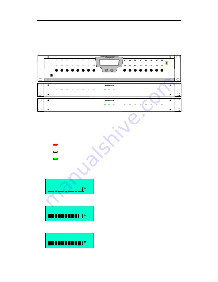
The diagram above shows how the LCD, soft keys and soft
LEDs are assigned when you turn the unit on for the first time.
You can plug your test source such as a music CD into the XLR
inputs, and route the XLR outputs to your system amplifiers.
You should see the source signal displayed on the left hand
side soft LEDs. Note that the input preamp gains default to
0dBu line level sensitivity with pad selected and phantom
power off. To properly test microphone sources you need to
run iDR System Manager software and correctly set the gains.
The channel faders default to fully off. The soft keys are
assigned as level up/down selects to move the input and
output channel faders up and down. Press the soft key for the
channel you want. Now use the two middle keys to scroll the
volume up or down. These time out after 2 seconds of
inactivity. You should see the level displayed as a bar and
number on the LCD display.
To get audio to pass through the unit you need to raise both
the input fader and the required output fader. In this default
configuration all inputs are routed through the matrix to all
outputs. You can use one input to test each output by raising
the output levels in turn. Similarly, you can use one output to
test all input sources. The right hand side soft LEDs display
output signal level.
The levels can be adjusted from ‘0’ (off) to ‘100’ (+5dB boost).
To set the fader to its 0dB unity position raise the level bar until
it reads ‘92’. Note that all the channel processing such as
equalisers and compressors is set flat or out. If you set both
the input and output levels to ‘92’ then you should get 0dB
unity gain through the unit.
With the face plate removed you can use the Setup menus to
listen to selected points in the channels using the stereo
monitor and headphones outputs, adjust the time and day
setting, and enter the communication settings ready to connect
your PC.
For information on configuring the system run the iDR System
Manager software and refer to its Help file.
I/P1 LEV 92
I/P1 LEV 100
I/P1 LEV 0
Fader off
Fader 0dB
Fader +5dB
Green
Yellow
-24dBu signal present
0dBu normal level
+14dBu 4dB below clipping
Red
Signal Meters
AUDIO INPUT EXPANDER
iDR-in
AUDIO OUTPUT EXPANDER
iDR-out
Allen & Heath
Wed 13:44:08
DR-8
AUDIO MIX PROCESSOR
1
2
3
4
5
6
7
8
INPUT LEVEL UP/DOWN
NOT USED
INPUT METERS 1-8
1
2
3
4
5
6
7
8
OUTPUT LEVEL UP/DOWN
NOT USED
OUTPUT METERS 1-8
< LEVEL >
INPUT METERS 9-16
9
10
11
12
13
14
15
16
OUTPUT METERS 9-16
9
10
11
12
13
14
15
16
Содержание iDR-8
Страница 48: ...48 IDR 8 User Guide ...


