DX32 Getting Started Guide
7
AP10242 Issue 3
3.
Front Panel
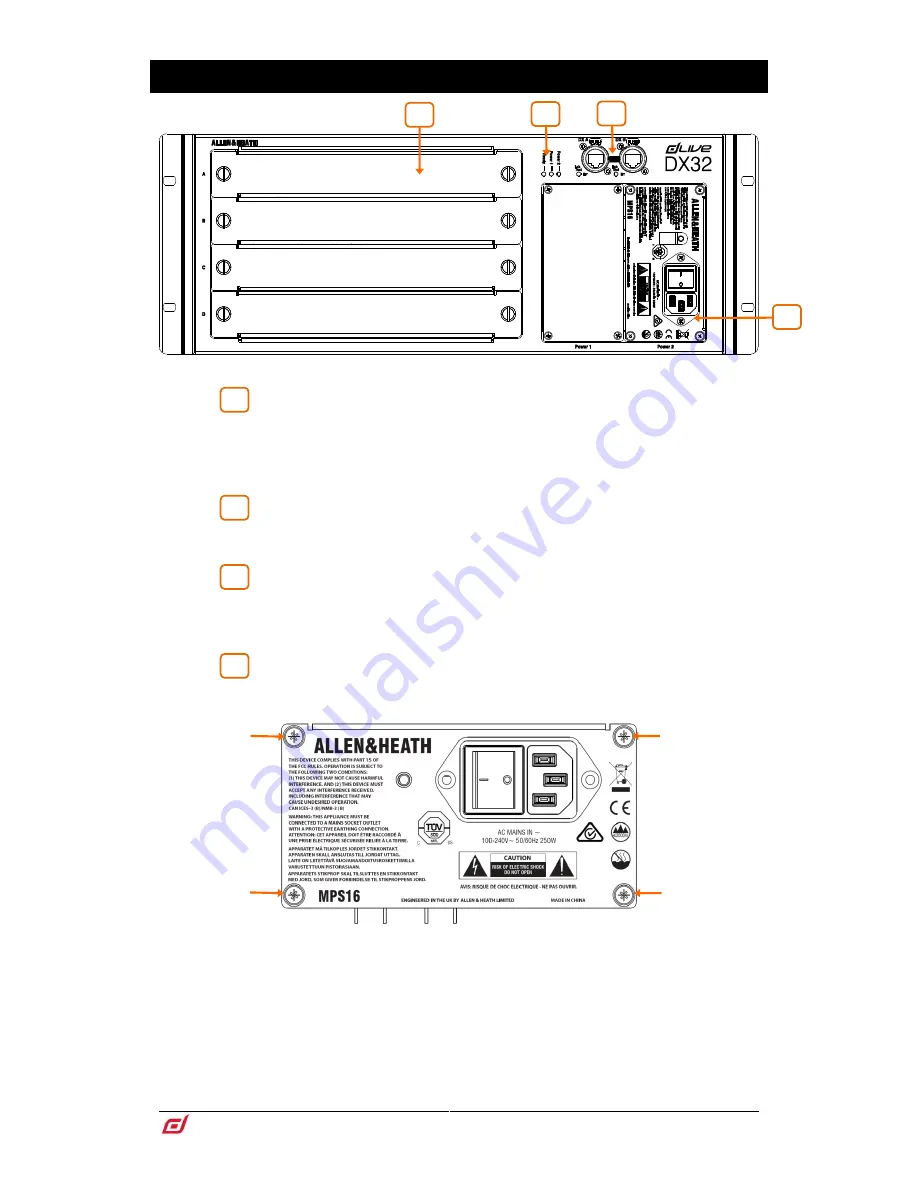
I/O modules
– 4x slots for fitting 8ch analogue or digital I/O modules. To fit
a module, switch the expander off, remove the blank panel by loosening the 2 thumb
screws, slide the module into the slot and press it firmly into the mating connector,
then secure it by tightening the thumb screws.
Use the dLive
I/O
screen to patch signals from or to the DX expander.
Status indicators
– Power ON indicators for the 2 power supplies. The
Ready indicator lights up when the output sockets are ready to pass audio after power
up.
DX links
– Dual redundant EtherCon ports for connection to a dLive MixRack
or Surface over Fast Ethernet (IEEE 802.3 Layer 2 compliant). A single Cat5e (or
higher) cable carries 32x32 channels of 96kHz audio and control. Use two cables for
redundancy.
Power Supply
– Hot swappable power supply with mains IEC socket and
On/Off rocker switch. To remove or replace, loosen the 4 screws indicated below and
slide the PSU out of the slot.
DX Expanders ship with one PSU fitted. A second PSU can be fitted for redundancy
(part number MPS-16). Remove the 4 screws securing the blank panel using a star
Torx T8 screwdriver, slide the PSU into the slot, and tighten the 4 screws indicated
above. The Expander will automatically switch between the supplies without
interruption to the audio should one fail.
Heed the safety warnings printed on the panel.
A plastic P-clip cable clamp is provided to secure the mains cable. Slot the cable in
or lock it in place using a star Torx T20 screwdriver to refit the clamp around the cable.
1
2
3
4
3
1
4
2


