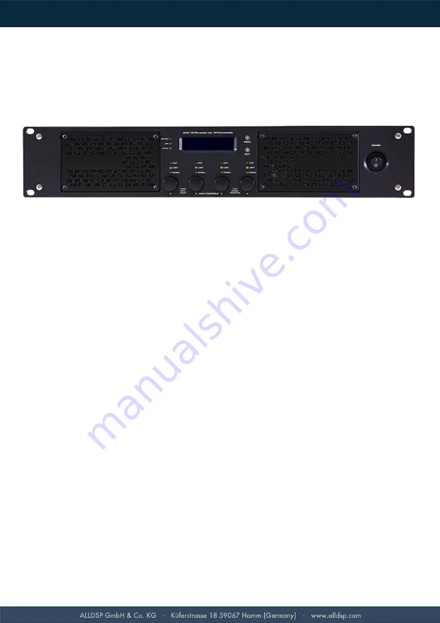
ALLDSP SMA-6P2408
1. Overview of Connectors and Controls
In addition to the available features described in this manual, you also have the option of controlling the
processor remotely over your network. Please refer to the Software Manual for details.
1.1. Front Panel
1.1.1. Input VU Meters
There are four independent input meters available. The LEDs indicate the signal level at the inputs, in dBu,
after the input gain faders. The Peak LED lights when the input level e20dBu, and blinks slowly
when the input is muted.
1.1.2. Function Buttons: Menu, Exit
Press the Menu button to enter the System Menu. Press Exit to go one level up in the system menu or in the
channel menu.
See section three for a detailed description on the functions of each of these buttons.
1.1.3. Rotary Encoders
The rotary encoders have several functions, depending on the currently visible menu item on the LCD
display.
In the default state, push the encoder to mute or unmute the corresponding input. Push and hold the encoder
to enter the channel menu.
When setting items in the channel menu (e.g. gains etc), pushing a rotary encoder selects the corresponding
channel and shows the parameter on the screen.
When editing the system menu, only the encoder for channel 1 is active and is used to navigate the menu.
When values are changed, the DSP is updated in real-time.
1.1.4. Power Switch
The Power Switch turns the SMA-6P2408 on and off. Note: The power switch is not a hard mains switch.
When powered off, the amplifier still consumes some power. To completely power off the amplifier,
disconnect the mains cord.
Page 4/11


