18
Function groups
Function groups
Manual ADQ-22/23-Serie Rev. 1.1
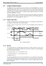
Example for bit pattern comparison:
• The reference bit pattern is defined in the
uiPortBitPatternValue
parameter of the
SADQIRQEnable
structure in function
adqEnableIRQ()
.
• Enable the interrupt by passing the boolean value TRUE in the parameter
bPortBitPatternCompare
of the structure
SADQIRQEnable
in function
adqEnableIRQ()
.
• As soon as all bits on the input port match the reference bit pattern,
an interrupt is triggered.
• The interrupt event is evaluated with parameter
bPortBitPatternCompare
of the
structure
SADQIRQStatus
in the function
adqWaitIRQ()
. TRUE indicates that bit
pattern equality is present.
3.2.3.3.3 Supply voltage missing
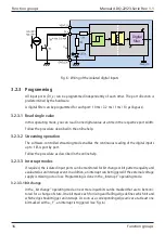
If required, an interrupt can be triggered in the absence of an external power supply
(VEXT_DI < 12.1 V).
3.2.3.3.4 Supply voltage too low
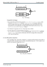
If necessary, an interrupt can be triggered if the external voltage supply is too low
(VEXT_DI < 8 V).
3.3 Isolated digital outputs
The
ADQ-22
has 2 isolated digital output ports with 16 bits each and the
ADQ-23
has 2 iso-
lated digital output ports with 8 bits each. The outputs are equipped with a power FET in
the high path that switches up to 0.6 A per channel. The isolation voltage against PC ground
is 500 VAC
eff
.
3.3.1 Wiring
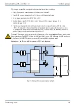
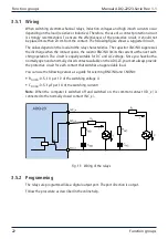
The outputs are designed for the usual high level of 24 V (UOH = 11..35 V) in control technology.
The max. output current IO is 0.6 A per channel. To increase the output current, several outputs
can be connected in parallel. A ground reference to the external output circuitry must be es-
tablished via GND_EXT. The digital output section and the digital input section use GND_EXT
together.

