


5
www.observint.com
© 2019 Observint Technologies. All rights reserved.
Run as
administrator
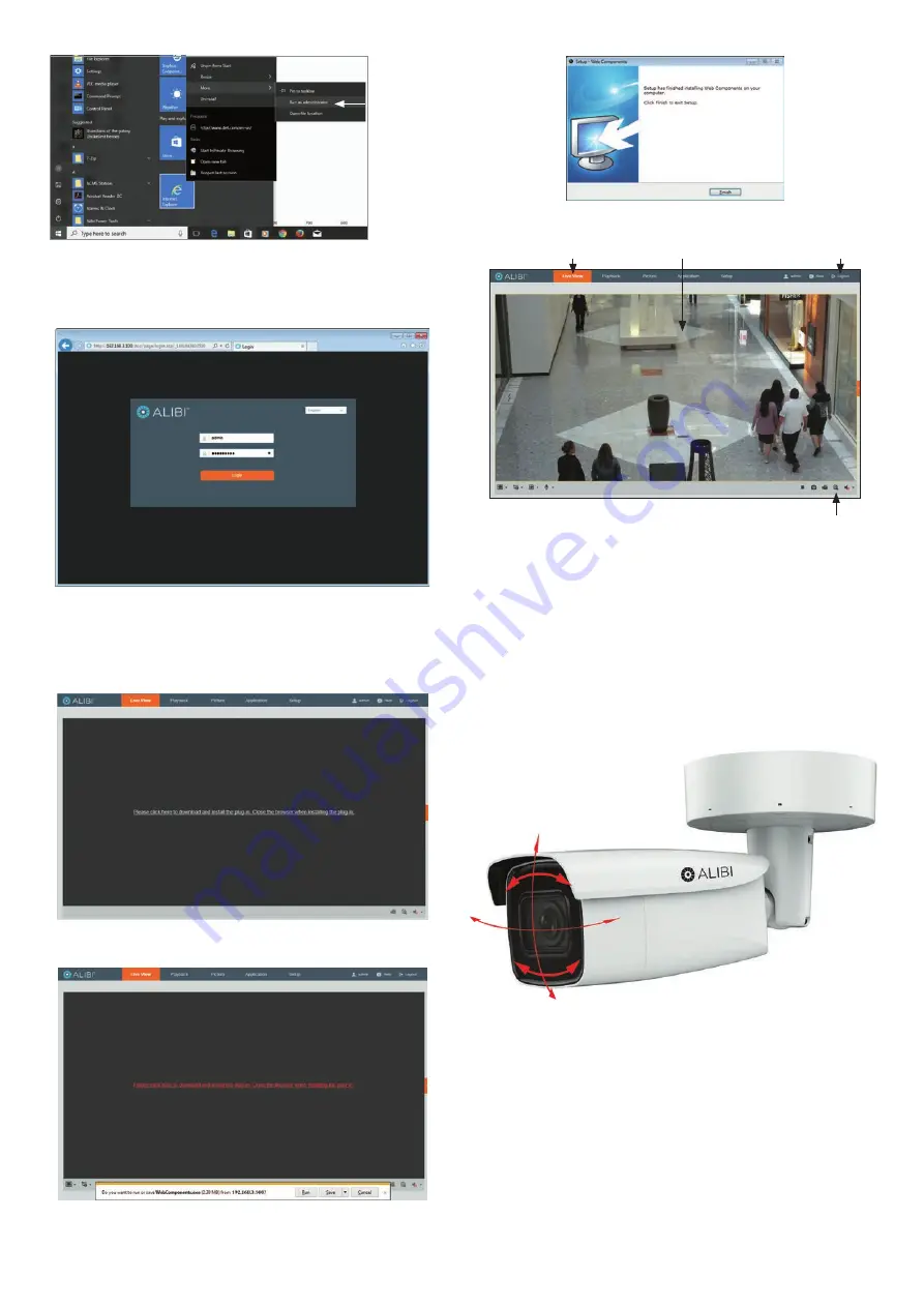
To login to the camera from a computer on the same LAN:
1.
Open your Microsoft Internet Explorer (IE) browser on your computer and enter the IP address of
the camera in the URL field. In the example below, the IP address of the camera is 192.168.3.100.
2.
In the login window, enter
admin
for the
User Name
and the password you created in the
Password
field, the click
Login
.
3.
If this is the first time you are logging into a camera, you may see the message in the following
screen. If this appears, follow the sub-steps below.
a.
Click on the message to install the plugin.
b.
In the message bar at the bottom of the screen, click
Run
. Follow the on-screen
instructions to install
WebComponents
. When the following screen opens, click
Finish
.
The Live View screen with the camera video image should appear.
Capture, Record, Zoom icons
Screen select tabs
Logout button
Live View image
Step 7. Adjust camera pan, tilt and rotation
Adjust the camera pan, tilt and rotation to point the camera at your surveillance target. When pointing
the camera, use the
Live View
display on a recorder or remote login. You can also attach the BNC video
maintenance cable to the connector on the maintenance panel, and then attach it to CVBS monitor to
see a live view video from the camera.
1.
While observing live video from the camera, use the L-wrench to loosen the adjustment bracket
lock screw on the back of the adjustment bracket until the camera is free to move and rotate. The
location of the lock screw is shown in the photos on page 1 of this guide.
2.
Point the camera at your surveillance target, changing the pan, tilt and rotation as needed. Be
certain to stay within the specified pan, tilt and rotation ranges of the camera. See below.
Pan range: 0˚ ~ 355˚
Tilt range: 0˚ ~ 90˚
Rotation range: 0˚ ~ 355˚
3.
Tighten the adjustment bracket lock screw to securely hold the camera in place.
Step 8. Verify PTZ functionality
Use the PTZ control panel to exercise the zoom and focus functionality of the camera. Accessing to the
control panel depends on whether the camera is installed as a device on a LAN or if it is connected to a
NVR. Select the installation type below for your camera to complete this step.
For cameras installed on a LAN
1.
Log into the camera and then open the
Live View
window.


