background image

18

Minigraf M3

6.6

ORDINARY MAINTENANCE

The following operations must be performed at the times indicated  below. Not observing  the  following instructions exonerate
the Producer from any responsibility regarding the warranty.
The operations described here below, even if simple, must be executed by qualified personnel.
The scheduled ordinary maintenance includes overhauls, checks and interventions that, to prevent stops and breakdowns,
keep the system workoing properly:

Lubrication state of the machine

Wear and tear parts state

TAB 6.6 A

6.7

EXTRAORDINARY MAINTENANCE

Listed below are  the operations that need the intervention of Alfamacchine or your local distributor’s Technical Assistance
(see the paragraph 1.2). You can also use qualified staff authorized by the Producer
The extraordinary maintenance includes interventions to be performed in exceptional cases:

Breakage

Revisions

TAB. 6.7 A

6.5

LUBRICATION

Use preferably CASTROL MAGNA GC 32 or equivalent oil
Furthermore, we recommend to lubricate the driver blade every 200 working hours.

Unsuitable lubricants may cause valve seal problems (seals may become too large) and consequent Valve
jamming.

Maintenance

V-nail driver blade

Movable parts lubrication

V-nails claw heads

“L” shaped supports (V-nails
guide)

Description

Replacement every 1.000.000 V-nails shot

Lubricate the driver blade every 200
working hours

Replacement every 5.000.000 V-nails shot

Replacement every 5.000.000 V-nails shot

Machine state

Isolation for maintenance

Isolation for maintenance

Isolation for maintenance

Isolation for maintenance

MAINTENANCE

Valves and Reducers

Frontal and vertical clamping
gaskets

DESCRIPTION

Suggested replacement every 6/8 million of
V-nails shot

Replacement in case of leak of air

MACHINE STATE

Isolation for maintenance

Isolation for maintenance

Содержание MINIGRAF M3

Страница 1: ...1 Minigraf M3 MINIGRAF 3 INSTRUCTION HANDBOOK Alfamacchine Via dell Artigiano 12 47100 Forl Italy Tel 39 0543 482711 Fax 39 0543 480770 info alfamacchine com www alfamacchine com...

Страница 2: ...ENTS 10 4 4 UNPACKING 10 4 5 CONNECTIONS 10 4 5 1 Pneumatic connection 10 4 6 PRELIMINARY CONTROLS 11 4 7 MACHINE ARRANGEMENT 11 4 7 1 V Nails magazine loading 11 7 7 2 V nail guide head replacement t...

Страница 3: ...basis of a correct customer distributor relationship 1 6 1 Object and contents The goal of this handbook is to provide to the customer all the necessary information so that they can properly use the...

Страница 4: ...he maximum attention to the paragraph marked with this symbol It is requested to take a measurement data to check a signal The user is requested to check the proper positioning of any element of the m...

Страница 5: ...uilding lit aired and with a compact and flat floor The permitted temperatures go from 5 to 40 C with a humidity level not higher than 50 at 40 C or 90 at 20 C 2 6 LIGHTING Premises lighting must be c...

Страница 6: ...N 1 nail head mm 10 N 1 nail head mm 15 N 1 L shaped pressure pad N 1 Rounding pressure pad N 1Allen Wrench 5 mm for V nails head replacement N 1 Brass rod magnet to remove V nails 2 10 2Upgrading and...

Страница 7: ...rame assembling easier e g special fences for peculiar moulding shapes special clamps to ensure the mouldings are locked properly during V nail firing and so on These can be made at your local machine...

Страница 8: ...mp 3 6 STOP FUNCTIONS The machine stop functions are the following Fast clutch fitting stop Category 0 Foot pedal Stop Category 1 STOPCATEGORY0 It is obtained by disconnecting the fast clutch fitting...

Страница 9: ...ot painted 4 1 SHIPPING AND HANDLING The shipment must be performed by a professionally qualified staff The machine has to be shipped in a safe way to avoid any damage to its parts All the protections...

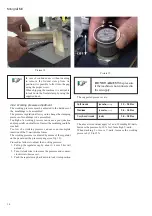
Страница 10: ...re 5 Picture 6 Once you have connected the machine with the pneumatic system check the operation of the foot pedal in the following way Pressing the foot pedal half way down activates the horizontal c...

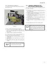
Страница 11: ...en the locking screw of the V nail guide head using the proper 5 mm Allen wrench the screw is on the opposite side from the V nails magazine See fig 10 Take out the V nail guide head Move the clawpush...

Страница 12: ...ment To properly position the mouldings to be assembled the Minigraf 3 is equipped with a 90 fence The fence can be shifted forward or backward in order to allow the proper positioning of the v nails...

Страница 13: ...itial position You will now be able to move it forward and backward To lock the bar it is sufficient to insert it into the proper peg located in the middle of the guide channel Proceed as follows to p...

Страница 14: ...l up the regulator cap by about 3 4 mm This will unlock it 2 Turn it clockwise to increase the pressure and counter clockwise to decrease it 3 Push the regulator cap back down to lock it into position...

Страница 15: ...tive shield is properly positioned see chapter 4 8 5 Press the pedal all the way down to insert the V nail If you want to insert 2 or more V nails one upon the other in the same position you must rele...

Страница 16: ...make excellent quality joints using different materials it has been necessary to manufacture different V nails types for different uses see attachment D V nails can be classified in three different gr...

Страница 17: ...ove glue or other residues from the V nail head and from the upper part of the driver blade Always keep the v nail magazine clean and without residues Remove any residues from the V nails guide L shap...

Страница 18: ...e includes interventions to be performed in exceptional cases Breakage Revisions TAB 6 7A 6 5 LUBRICATION Use preferably CASTROL MAGNA GC 32 or equivalent oil Furthermore we recommend to lubricate the...

Страница 19: ...working pressure V nails wrongly positioned into the magazine Guide channels damaged or jammed Claw pusher has insufficient thrust Claw head not suitable with V nails size Faulty V nails Insufficient...

Страница 20: ...nails Poor frames clamping the frame moves during the V nail insertion Wore and torn driver blade Jammed driver blade REMEDY Remove the surplus of oil and or condensation Replace the foot pedal valve...

Страница 21: ...RTS ORDERING We remind you that only a qualified technician can repair the machine Therefore we suggest the intervention of your local distributor orALFAMACCHINE s Center of TechnicalAssistance which...

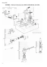
Страница 22: ...22 Minigraf M3 SCHEMES A Mechanic Schemes code DWG Nr 003 0 100 Rev 1 01 1997...

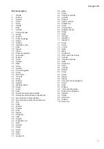
Страница 23: ...sure plate with caoutchouc 41 Rod 42 Knob 43 Washer 44 Support 45 Knob 46 Spacer 47 Protection 48 Valve 49 Support 50 Protection unit 51 Slide 52 Support 53 Screw 54 Screw 55 Head 56 Piston 57 Gasket...

Страница 24: ...24 Minigraf M3 Ref Description 1 Regulator 2 Pressure Gauge 3A Valve 228 52 11 1 or 2411520016 3B Valve 228 52 11 1 or 2411520016 4 Pressure Regulator SCHEMES B Pneumatic Scheme 5 Valve 0ALF 100...

Страница 25: ...25 Minigraf M3 SCHEME C Plates location...

Страница 26: ...ar Maple Pine Other materials Vertical grain MDF Polystyrene PVC HW Suitable for soft wood such as Oak Ash Hickory Pecan Maple Cherry Ramin Other materials Horizontal grain MDF SOFT WOOD HARD WOOD A B...

Отзывы: