3 Installation
Study the instructions carefully and pay special attention to the warnings!
The valve has ends for welding as standard.
Weld carefully/aim at stressless welding to avoid deformation on sealing areas.
Check the valve for smooth operation after welding.
Step 3
Bottom of tank
Bottom of tank
Tank flange (standard)
Stub flange (option)
A
1
TD 449-253_1
1
1
TD 449-252_1
1 = Caution
1 = Caution
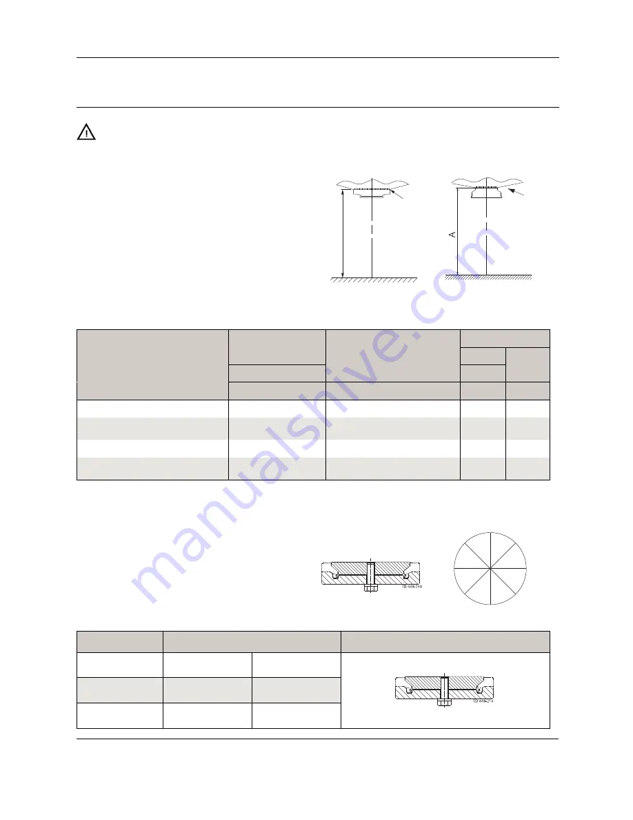
Before welding the flange into the tank please note:
1. Maintain the minimum clearances "A" so that the actuator with
the internal valve parts can be removed - please see later this
section!
If there is a risk of foot damage, Alfa Laval recommends to leave
a distance of 120 mm (4.7”) below the valve (look at the specific
built-in conditions).
Min. dimension Unique TO (all measures in mm) (1mm = 0.0394”)
Longstroke
DN/OD
DN/OD
2”
2½”
3”
4”
DN
2½”
3”
DN
Size
51
63.5
76.1
101.6
50
65
80
100
125
150
63.5 76.1
63
80
with tank flange (A
1
)
579
646
659
753
577
652
667
755
805
890
700
713
706
721
with external cleaning and tank flange (A
1
)
616
686
699
813
614
692
707
815
865
N/A
740
753
746
761
with stub flange (A)
588
655
668
762
586
661
676
764
814
899
709
722
715
730
with external cleaning and stub flange (A)
625
695
708
822
623
701
716
824
874
N/A
749
762
755
770
If ThinkTop is mounted, add 180 mm (7.1”) to dimension
N/A = Not available
2. Always use welding jig (can be ordered separately at Alfa
Laval) to ensure precision of flange after welding.
Only use pulsed arc welding and remember no gap
between flange and tank plate.
Tack weld always on the opposite side (8 segments with
filler metal).
Weld root if possible without filler metal. Welding of the
final run must be done in 8 segments to avoid crack.
Remember NOT to dismount welding jig before flange is
cold.
Welding jig
TD 449-244_1
4
8
5
1
2
6
7
3
Item no.
Size
Welding tool for tank flange
2”
9613-0999-01
51 mm
DN50
2½” - 3 “
9613-0999-02
63.5 - 76.1 mm
DN65 - DN80
4”
9613-0999-036
101.6 mm
DN100 - DN150
12
Содержание Unique TO
Страница 2: ......


