A Tour of the MultiMix USB
2
17
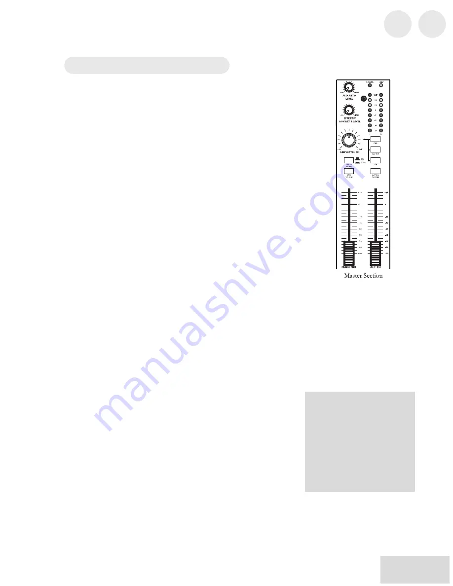
Master Section
The Master Section is the heart of the mixer, where the channel
inputs and aux returns all are mixed together and routed in various
ways.
Main Mix Fader
The signals from all channels and aux sends—excluding those that
are muted—are sent to the main mix. The MAIN MIX fader is the
one you’ll use to control the overall level of those combined
signals. This fader affects the levels of the signals sent to the
MAIN MIX OUT, the DIGITAL OUT (12FXD and16FXD
models only) and the 2-TRACK OUT. In its lowest position the
signal is cut off completely, and in the uppermost position you get
an additional 10dB of gain. In the 0 position the fader is at unity
gain.
Alt 3/4 Fader
This fader controls the output of the Alt 3/4 bus.
2TK To Mix
When you press this switch, the signal coming in through the 2-
TRACK IN gets routed to the MAIN MIX, joining whichever
other signals are already part of the main mix. Used this way, the
2-TRACK IN effectively becomes another stereo channel (but
without all the extras like pan, EQ, etc.).
Alt 3/4 To Mix
This switch adds the signal from the Alt 3/4 bus to the main mix
bus.
Solo Mode
The SOLO MODE switch affects the signals of channels whose
PFL / SOLO switches are engaged. When the SOLO MODE
switch is in the up position, you’re in PFL, or pre-fader listen
mode. This means that you’ll hear the signals of all soloed
channels as they sound before they pass through their respective
faders. You’ll need to be in PFL mode when you’re setting levels
(see “Setting Channel Levels,” page 12. This mode is post-EQ.
When the SOLO MODE switch is engaged (in the down
position), you are in SOLO mode. This means that you will hear
the output of every soloed channel (after it passes through its
fader, pan and EQ).
The purpose of seeing a
soloed channel’s level on the
LED meters is so that you can
see the true level of that
channel’s signal. For that
reason, the HDPH / CTRL
RM knob does not change the
LED meters’ reading—it
changes only the level at
which you’re listening to the
soloed channel.
2
A Tour of the MultiMix USB
18
HDPH / CTRL RM
The HDPH / CTRL RM knob controls the level of the signal
being sent to the CTRL RM OUT and the PHONES output. The
level of this signal is represented by the LED meters. The switches
to the right of the HDPH / CTRL RM knob determine the source
of the control room mix as explained below. You can use these
switches in any combination. If none is selected, you’ll hear silence
in the control room mix and the LED meters won’t light up.
The “CTRL RM” in the name of this knob refers to the fact that it
controls the signal that typically is sent to the control room
monitors of a studio, where someone—usually an engineer—is
working the mixer. However, don’t be intimidated if you’re using
this mixer in your bedroom, which probably isn’t equipped with a
control room. In this scenario, you can use headphones or connect
the CTRL RM OUT to your speakers.
MIX Switch
Pressing the MIX switch routes the main mix to the control room
level control. When you engage this switch, the channels and aux
sends will pass through the MAIN MIX fader and then through
the HDPH / CTRL RM level control. You can then keep the
MAIN MIX fader set to unity gain for optimal recording, and the
HDPH / CTRL RM level control set to a more comfortable
listening level if necessary.
ALT 3/4 Switch
When you press the ALT 3/4 switch, the signal from the ALT 3/4
stereo mix bus is routed through the HDPH / CTRL RM level
control.
2TK Switch
If you want to monitor the signal coming in from the 2-TRACK
jacks, press the 2TK switch.
Aux Ret A Level
This is the level control for the signal returning to the mixer via
AUX RETURN A.
Effects / Aux Ret B level
If you are using one of the Multimix’s internal effects, this knob
controls the effect level. If AUX SEND B is connected to an
external device, this knob controls the level for AUX RETURN B.
When you solo a channel via
its PFL / SOLO switch, that
channel’s signal will override
your control room mix
selection. You then will hear
only that channel in the
control room and the
headphones.
Содержание MultiMix12USB
Страница 1: ...Reference Manual ...
Страница 2: ...This page intentionally left blank 10 20 30 40 50 60 70 80 90 100 ...
Страница 5: ...Table Of Contents 3 Alesis Contact Information 40 T 4 T ...
Страница 6: ...s 3 Table Of Contents 4 This page intentionally left blank ...
Страница 12: ...Introduction 10 This page intentionally left blank ...
Страница 28: ...s 4 25 4 Applications 26 This page intentionally left blank ...
Страница 32: ...g 5 29 d n r 5 Troubleshooting 30 This page intentionally left blank ...
Страница 35: ...7 Block Diagrams 33 7 B 34 ...
Страница 36: ...33 7 Block Diagrams 34 ...
Страница 39: ...Glossary 37 opposite of dry G 38 T ...
Страница 40: ...y 37 Glossary 38 This page intentionally left blank ...


