background image


45 

September 14, 2018 

ACCESSORIES 

DEVELOPMENT KIT 

Part Number: DEVKIT-RIDEPLAYER 

We offer this kit to enable users to quickly bench test or build mockups with RidePlayer units.  This kit includes 
prefabricated cables for each of the connectors on the unit.  It also includes a 24V/20A DIN Rail power supply to 
power up the unit. 

We recommend that new users order at least one of these kits to get started with RidePlayer development.  Since 
most on-board audio applications use highly customized cabling, this kit is probably not practical for wiring up an 
entire fleet of ride vehicles. 

CONNECTOR KIT 

Part Number: CONKIT-RIDEPLAYER 

This kit provides a full set of blank Molex connectors and pins for the majority of RidePlayer’s connectors.  We 
offer this kit as a convenience to fabricators so that the individual parts don’t have to be researched and ordered.  
Unlike the Development Kit, the Connector Kit is intended to be used for fleet deployments.  We recommend 
ordering a Connector Kit for each RidePlayer in the ride vehicle fleet. 

M12 X-CODED ETHERNET CABLE 

Part Number: CM12X-2M 

This is an M12 X-Coded patch cable that allows RidePlayer to connect to an M12 X-Coded Ethernet switch.  Our 
stock cable is 2 Meters (6.5ft) in length.  For fleet deployments, we have the capability to manufacture cables to 
custom lengths to suit your application. Please contact us for quotes for custom length M12 X-Coded cables.   

M12

à

RJ45 ETHERNET ADAPTER 

Part Number: CM12X-RJ45F 

This is an adapter that converts from the M12 X-Coded connectors of RidePlayer to a standard RJ45F Ethernet 
connector. 

POWER SUPPLY 

Part Number: PSD24V20A 

This supply is capable of providing RidePlayer with the recommended 24VDC/20A power source.  It accepts an 
input between 100-240VAC and is designed to mount on a DIN Rail alongside the RidePlayer.


Содержание RidePlayer

Страница 1: ...RidePlayer User s Guide September 14 2018 THE ULTIMATE ON BOARD AUDIO AND SHOW CONTROL SOLUTION ...

Страница 2: ...GETTING STARTED 8 WIRING AND CONNECTIVITY 8 NETWORK CONFIGURATION 10 CONTROLLING WITH WINSCRIPT LIVE 12 HARDWARE INFORMATION 14 OVERVIEW 14 DISPLAY AND NAVIGATION BUTTONS 14 INDICATOR LEDS 19 CONNECTORS 22 SYNCHRONIZATION 30 PHASE LOCKED CLOCKS 30 PRECISE TRIGGERING 31 SYSTEM ARCHITECTURE 33 SYNC CONFIGURATION 34 NETWORK AUDIO PASS THROUGH 36 RIDEAMP INTEGRATION 40 MOUNTING 41 SPECIFICATIONS 42 ...

Страница 3: ...2018 CONTROL 42 AUDIO 42 SYNCHRONIZATION 43 PHYSICAL 43 BLOCK DIAGRAM 44 ACCESSORIES 45 DEVELOPMENT KIT 45 CONNECTOR KIT 45 M12 X CODED ETHERNET CABLE 45 M12àRJ45 ETHERNET ADAPTER 45 POWER SUPPLY 45 PRODUCT PHOTOS 46 ...

Страница 4: ... ability to route crossfade and mix those tracks to any of the 16 outputs This polyphonic capability allows any combination of discrete playback of tracks like background music vocals and sound effects all mixed on a single audio output Each audio output is also equipped with powerful DSP capabilities that enable you to tune audio characteristics on site Audio distribution options are plentiful Th...

Страница 5: ...Serial Ports o Serial GPS DMX Power Supply Voltage Monitoring Analog Voltage Sense Input AUDIO FEATURES This product is equipped with an incredibly powerful audio playback system that includes many advanced features designed to eliminate the need for external components like DSPs amplifiers multiple audio players etc These features enable high quality surround sound effects to enhance the guest ex...

Страница 6: ... enables it to endure the harsh environments of coaster and dark ride applications It offers flexible mounting options industrial grade connectors DC power input and a rock solid chassis design Physical features include Vibration impact resistant design o Coasters Dark Rides Parade Floats Parking Trams etc Rugged Locking Molex connectors M12 X Coded Ethernet Connectors Dimensions 9 5 W x 13 1 L x ...

Страница 7: ...plication Notes that give you detailed documentation and examples for how this product is used in common types of themed entertainment projects You ll also find the latest downloads for software firmware drawings 3D models cutsheets and other helpful resources on our Support page The Knowledge Base is especially handy for common questions and helpful troubleshooting tips And last but certainly not...

Страница 8: ...ectors and a power supply so you spend less time crimping and get right to bench testing your RidePlayer POWER Our engineers are working around the clock to eliminate the need for those pesky Electrons However until they inevitably succeed RidePlayer needs power to work properly You ll want to start by connecting RidePlayer s power input to a 24VDC power source like a battery super capacitor or be...

Страница 9: ...bles are also available for individual purchase from Alcorn McBride Using the M12 cable you ll want to connect the Primary Control port of RidePlayer to your network switch or computer Aside from the vibration resistant M12 connector this is no different than connecting to any other network device When the unit is powered on you will see a link indicator illuminate on RidePlayer s top panel to ind...

Страница 10: ...hose that just wish to connect a computer directly to RidePlayer the easiest way is to set your computer to a static IP address that is compatible with RidePlayer s default network settings For example this configuration would work nicely for your computer CONFIGURING STATIC IP WINDOWS 10 1 Right click on the Windows icon in the bottom left and select Network Connections 2 Select Change adapter op...

Страница 11: ...ss CONFIGURING STATIC IP OS X 1 Click on the network icon in the OS X menu bar and select Open Network Preferences 2 Select the network interface that is connected to RidePlayer from the available interfaces on the left 3 Configure the network interface Manually specify an IP address of 192 168 0 100 and a Subnet Mask of 255 255 255 0 as indicated in the screenshot below 4 Click Apply to enable th...

Страница 12: ...nScript Live and click the Connect button on the splash screen 2 Your RidePlayer unit should automatically appear in the connection list Click it once to select and then click the OK button to connect 3 Select Retrieve and click OK WinScript Live will then load the project currently stored on the RidePlayer 4 Double click on the Media Files resource listed on the left hand side of WinScript Live T...

Страница 13: ...en added to the list you can click on the Sync button to transfer them to the unit You can also right click on the file and click Send Media File o Much of RidePlayer s capabilities require the use of its powerful show control engine This includes advanced scripting capability timeline features and device control To learn more the detailed documentation of our show control platform is built right ...

Страница 14: ... primarily used to share application specific information i e Location Scene 2 from the show control script However this display also offers a full menu system that can be accessed using the navigation buttons located adjacent to the display MAIN MENU This menu provides access to the following sub menus Audio View Audio settings and control Gain and Mute Control Monitor show control performance an...

Страница 15: ...pts CPU Load View current load of show control processor Serial Mode View mode of operation for multi purpose serial port SYNC MENU Sync Source View sync clock reference Internal PTP NTP GPS SMPTE LTC Genlock Frame Rate View operating frame rate of show control core PTP Master View state of PTP clock distribution No Yes NTP Server View state of NTP Server clock distribution No Yes IP Genlock Out V...

Страница 16: ...No additional information o PTP GrandMaster ID None or XXXXXX XXXX XXXXXX Device ID XXXXXX XXXX XXXXXX PHC Master Offset In nS Mean Path Delay In nS o NTP Server Address o GPS PPS Active 1Hz 5Hz etc o SMPTE LTC No additional information o Genlock Genlock Input Format of Genlock input signal i e 1080p60Hz NETWORK MENU Primary Control View Status and Configure the Primary Control port Secondary Cont...

Страница 17: ...w Configure DNS address Control MAC View MAC address for Show Control Ethernet interface Media Sync MAC View MAC address for Media Sync Ethernet interface Link Current link status of network port AUDIO NETWORK MENU Device Name View Configure current Dante AES67 Device Name DHCP Enable Disable DHCP network configuration IP View Configure IP address Subnet Mask View Configure subnet mask Gateway Vie...

Страница 18: ...irmware version of unit Build Build revision of firmware Status View status info such as temperature fan speed input voltage etc Format SSD Erase and Format internal SSD media Reset Settings Reset all configuration data i e network device name etc to factory defaults Reboot Reboot RidePlayer and re launch script ...

Страница 19: ... whenever the sync system is locked to the configured reference Live ON whenever WinScript Live is connected to the device SERIAL GPS These indicators blink to indicate activity on either the GPS serial port or the multi purpose serial port NETWORK These indicators display both network link and activity for all of the Control and Network Audio ethernet ports LED State Description OFF No network li...

Страница 20: ...ut is 9VDC GREEN Active Contact closure detected or voltage input is 9 24VDC OUTPUTS These indicators display the activation state of the 4 dry contact relay outputs Keep in mind that these are normally open NO relays so the contacts are closed when the output is in an Active state LED State Description OFF Inactive Relay contact is OPEN GREEN Active Relay contact is CLOSED ...

Страница 21: ...AUDIO These indicators display the status of all 16 audio outputs This includes playback activity and audio mute status LED State Description OFF No audio playback GREEN Audio playback in progress RED Audio output is MUTED ...

Страница 22: ...Mating Pins Molex 39000185 Recommended Wire 16 AWG Stranded Speakers 1 8 Single 25W Speakers 9 16 Single 25W Speakers 1 8 Bridged 50W Speakers 9 16 Bridged 50W SPK 1 1 SPK 9 1 SPK 2 1 9 SPK 10 1 9 SPK 1 9 SPK 9 9 SPK 2 2 10 SPK 10 2 10 SPK 2 2 SPK 10 2 SPK 4 3 11 SPK 12 3 11 SPK 2 10 SPK 10 10 SPK 4 4 12 SPK 12 4 12 SPK 3 3 SPK 11 3 SPK 6 5 13 SPK 14 5 13 SPK 3 11 SPK 11 11 SPK 6 6 14 SPK 14 6 14 ...

Страница 23: ...ecommended Wire 18 AWG Stranded Pinouts Line Outputs 1 4 LINE OUT 1 1 SHIELD 5 LINE OUT 2 2 SHIELD 6 LINE OUT 3 3 SHIELD 7 LINE OUT 4 4 SHIELD 8 Line Outputs 5 8 LINE OUT 5 1 SHIELD 5 LINE OUT 6 2 SHIELD 6 LINE OUT 7 3 SHIELD 7 LINE OUT 8 4 SHIELD 8 Line Outputs 9 12 LINE OUT 9 1 SHIELD 5 LINE OUT 10 2 SHIELD 6 LINE OUT 11 3 SHIELD 7 LINE OUT 12 4 SHIELD 8 Line Outputs 13 16 LINE OUT 13 1 SHIELD 5...

Страница 24: ...e used to monitor analog voltage levels between 0 10V Example applications include monitoring a secondary power rail i e 48VDC power rail for external amplifiers Connector Information Connector Type 2x2 Molex Mini Fit Jr Mating Connector Molex 0039012040 Mating Pins Molex 39000073 Recommended Wire 18 AWG Stranded Pinouts Analog In GND 1 Analog In 2 GND 3 Analog In 4 Connector Layout Wire Side View...

Страница 25: ... be configured for DMX lighting control or for generic serial control of RS232 RS422 devices Connector Information Connector Type 2x6 Molex Mini Fit Jr Mating Connector Molex 0039012120 Mating Pins Molex 39000073 Recommended Wire 18 AWG Stranded Pinouts GPS Port Serial DMX Port GPS PPS 6 Serial RS232 TX Serial RS422 TX DMX Out 9 GPS RS232 TX GPS RS422 TX 12 Serial RS422 TX DMX Out 2 GPS RS422 TX 5...

Страница 26: ...cess to the genlock interface of the RidePlayer The input will accept a Blackburst Composite Sync or Tri level video sync source The output will provide a Composite Sync signal that can be fed into other genlock capable devices Two DIP switches are provided to configure sync termination and sync input mode SMPTE LTC LTC IN 3 LTC IN 6 GND 2 GND 5 LTC OUT 1 LTC OUT 4 Termination Switch ON UP 75W Ter...

Страница 27: ...end 24VDC to achieve maximum output power for the built in amplifiers This input includes a built in 25A circuit breaker switch Connector Information Connector Type 2x4 Molex Mini Fit Jr Mating Connector Molex 0039012040 Mating Pins Molex 39000185 Recommended Wire 16 AWG Stranded Pinouts Power Input PWR 1 GND 2 PWR 3 GND 4 Connector Layout Wire Side View ...

Страница 28: ... software configured for two modes of operation contact closure or voltage Connector Information Connector Type 2x8 Molex Mini Fit Jr Mating Connector Molex 0039012160 Mating Pins Molex 39000073 Recommended Wire 18 AWG Stranded Digital Inputs IN1 1 IN1 9 IN2 2 IN2 10 IN3 3 IN3 11 IN4 4 IN4 12 IN5 5 IN5 13 IN6 6 IN6 14 IN7 7 IN7 15 IN8 8 IN8 16 Connector Layout Wire Side View ...

Страница 29: ...ormally open NO and include inline self healing polymer fuses that are rated to 900mA Connector Information Connector Type 2x4 Molex Mini Fit Jr Mating Connector Molex 0039012080 Mating Pins Molex 39000073 Recommended Wire 18 AWG Stranded Digital Outputs OUT1 A 1 OUT1 B 5 OUT2 A 2 OUT2 B 6 OUT3 A 3 OUT3 B 7 OUT4 A 4 OUT4 B 8 Connector Layout Wire Side View ...

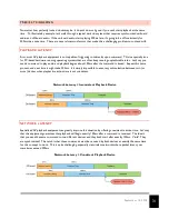
Страница 30: ...he exact same time When you meet up again a week later you might be surprised to see that the watches are likely many seconds off from one another Why Well there are many contributing factors such as crystal frequency precision temperature mechanical tolerance etc Bottom line the watches run at slightly different rates and this difference compounds over time The same concept also holds true with t...

Страница 31: ...d to play audio and playback begins about 100ms after the command is issued Repeat this same process and next time it might take 200ms It is simply impossible to ensure synchronization between two or more devices when playback reaction time is not consistent Network Latency Inconsistent Playback Device NETWORK LATENCY Specialized AV playback equipment can greatly improve this situation by offering...

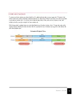
Страница 32: ... maintain a very precise master clock In other words all devices keep track of the current hour minute second and millisecond with a precision as tight as a few nanoseconds With this approach playback times are scheduled based upon this shared master clock This greatly reduces the impact of network latency because the time that the command arrives is irrelevant as long as it arrives before the sch...

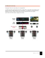
Страница 33: ... picture here is a representation of a typical dark ride system that uses the Ride Control PLC as the PTP clock master for the entire attraction In this example the V16X BinloopX and RidePlayer would all be configured to lock directly to the PLC s master PTP clock to ensure perfect synchronization for all show systems throughout the attraction ...

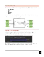
Страница 34: ...synchronize the entire system LOCKING TO A SYNC REFERENCE Within your WinScript Live project you can configure an external sync reference by accessing the ConfigurationàSync menu option Here you can choose the reference source you want this unit to synchronize with and specify a master Frame Rate for the show control system If your application does not require the use of an external reference cloc...

Страница 35: ...nc menu One important thing to note is that it is possible for SyncCoreä products to lock to an external reference and simultaneously distribute another type of reference A common example of this would be configuring a V16X to lock to an external PTP Master i e Ride Control PLC This V16X may then need to synchronize precisely with RidePlayers over a wireless network which may not support PTP distr...

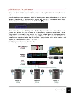
Страница 36: ...er s internal playback system This mode empowers media designers to feed the output of their editing suite directly to RidePlayer s outputs to effectively preview their content without having to load audio files to the unit To explain how this mode affects RidePlayer let s first look at the audio signal path during normal operation As you can see during normal operation the internal audio player o...

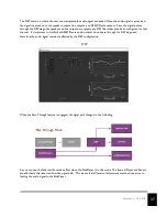
Страница 37: ...hat channel It s important to clarify that AES67 Dante audio outputs do not pass through the DSP stage and therefore the audio signal remains unaffected by the DSP configuration When the Pass Through feature is engaged the signal path changes to the following As you can see the faders will not take effect when the RidePlayer is in this mode The Internal Player and Faders are effectively disconnect...

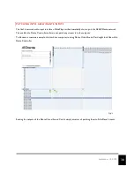
Страница 38: ...e AES67 Dante network This enables the Dante Controller software can patch any stream into these inputs To illustrate a common example this is what a computer running Dante Virtual Sound Card might look like within Dante Controller Routing the outputs of the Dante Virtual Sound Card is simply a matter of patching them to RidePlayer s inputs ...

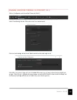
Страница 39: ...network audio Click the Audio Settings tab and check Enable network audio passthrough mode Click OK to accept the changes and voila The AES67 Dante input is now being routed directly to RidePlayer s outputs Once the mix is complete the media designer can export WAV files to be loaded onto RidePlayer and the Network Audio Bypass Mode can be disabled to resume normal operation ...

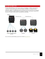
Страница 40: ...while RideAmp units greatly enhance its amplification capabilities The AES67 Dante network audio interfaces allow you to daisy chain up to 8 RideAmp units while maintaining an all digital signal path with rugged M12 connections These network connections also allow you to remotely control and monitor the RideAmp units via RidePlayer For more information about RideAmp please visit our website at www...

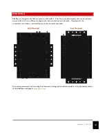
Страница 41: ...mount the unit in two different configurations side mounted and end mounted This allows for the conservation of vertical or horizontal space on the ride panel as needed For exact measurements and mounting hole locations drawings and models are available in the Downloads section of the RidePlayer web page at www alcorn com Side Mounted End Mounted ...

Страница 42: ...ling fuses 8 pin Molex Analog Inputs 1 x Power Supply Voltage Sense 0 28VDC Internal 1 x General Purpose 0 10VDC 4 pin Molex Show Memory Removable SD Card w Captive Socket GPS NMEA 0183 waypoint triggering AUDIO Playback 64 sources 16 output channels x 4 layers of polyphony per channel 16 bit or 24 bit WAV 44 1kHz 48kHz Sample accurate DSP 9 band Parametric EQ High Pass Low Pass Notch Filters Phas...

Страница 43: ...Out 6 Pin Molex Frame Rates 23 976 24 25 29 97 30 47 952 48 50 59 94 60 GPS Type NMEA 0183 w PPS Clock Input Clock Accuracy GPS 1uS w 1ppB Free run accuracy PTP 1uS w 1ppB Free run accuracy Genlock NTP 1mS w 10ppB Free run accuracy PHYSICAL Size 9 5 W x 13 1 L x 3 3 H Weight 11 lbs Power 9 28VDC 24VDC 3A w Amplifiers Disabled 24VDC 20A w Amplifiers Enabled Circuit Breaker 25A Operating Temperature...

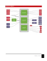
Страница 44: ...44 September 14 2018 BLOCK DIAGRAM ...

Страница 45: ...ividual parts don t have to be researched and ordered Unlike the Development Kit the Connector Kit is intended to be used for fleet deployments We recommend ordering a Connector Kit for each RidePlayer in the ride vehicle fleet M12 X CODED ETHERNET CABLE Part Number CM12X 2M This is an M12 X Coded patch cable that allows RidePlayer to connect to an M12 X Coded Ethernet switch Our stock cable is 2 ...

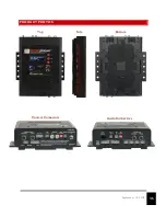
Страница 46: ...46 September 14 2018 PRODUCT PHOTOS Top Bottom Side Control Connectors Audio Connectors ...

Отзывы: