Mainboard PX915-DV
16
insert an expansion card which the interface is capable for PCI-E x16 specification (i.e., a graphics
card) onto the other slot, PCI-E1.
PCI Interface Slots: PCI1/2
This mainboard provides two standard 32-bit PCI slots. PCI stands for Peripheral Component
Interconnect and is a bus standard for expansion cards, which has supplanted the older ISA bus
standard.
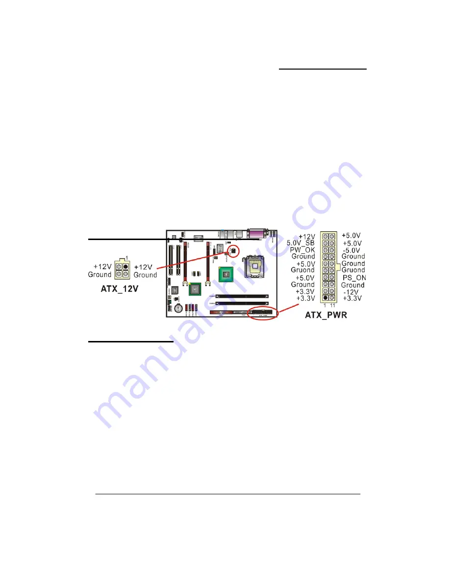
Power Supply Attachments
ATX Power Connector: ATX_PWR
、
ATX_12V
This mainboard provides two ATX power connectors, a 24-pin ATX_PWR connector and a 4-pin
ATX_12V connector. You must use a power supply that has both of these connectors and both
connectors must be attached before the system is powered on. These power connectors support
several power management functions such as the instant power-on function. The connector pins are
described below.
Chapter 2. BIOS Setup
Introduction
ich resides in the BIOS firmware. The
tion. The configuration information is
after power-down.
evel support for standard devices such as disk drives, serial ports and
he PHOENIX-AWARD
TM
BIOS installed in your computer system’s ROM is a custom version of an industry
PHOENIX-AWARD
TM
BIOS includes additional features such as virus and password
rotection as well as special configurations for fine-tuning the system chipset. The defaults for the
This section describes PHOENIX-AWARD™ BIOS Setup program wh
Setup program allows users to modify the basic system configura
then saved to CMOS RAM where the data is sustained by battery
The BIOS provides critical low-l
parallel ports. As well, the BIOS controls the first stage of the boot process, loading and executing the
operating system.
T
standard BIOS. This means that it supports the BIOS of Intel
®
based processors.
This version of the
p
BIOS values contained in this document may vary slightly with the version installed in your system.


