background image

Rev. 9/27/2009 

Manual #001451 

28 


Operation 

High Speed Doors 

Содержание UltraSecure 3000

Страница 1: ...traReliable UltraAffordable Albany Door Systems A Company of Albany International Corp All Rights Reserved 1080 Maritime Drive Port Washington WI 53074 975 A Old Norcross Road Lawrenceville Georgia 30046 262 268 9885 www albanydoors com PN 001451 Rev 9 27 2010 Version 4 20 ...

Страница 2: ...this warranty Any changes made to product configuration without the ex press written approval from Albany Door Systems may null and void this warranty Albany Door Systems obligations under this warranty are limited to repairing or replacing the defective part including labor and Albany Door Systems shall not be responsible for any other losses or damages due to the operation of any door or parts c...

Страница 3: ...5 www albanydoors com support albint com Lawrenceville GA 945 A Old Norcross Road Lawrenceville GA 30045 Phone 800 252 2691 Fax 262 268 9895 Technical Support 262 268 9885 www albanydoors com support albanydoors com 3 Introduction 4 Product Description 7 Drawings 9 Inspection Plan 12 Safety Instructions 14 Troubleshooting 15 Maintenance 17 UltraSmart Control 25 Wiring 31 Wireless Safety System 32 ...

Страница 4: ...the likelihood and the potential severity of injury In addition a hazard symbol may be used to represent the type of hazard DANGER indicates a hazard that if not avoided will result in death or serious injury WARNING indicates a hazard that if not avoided could result in death or serious injury CAUTION indicates a hazard that if not avoided might result in minor or moderate injury CAUTION when use...

Страница 5: ... supported by tensioned springs located within the side columns The door closes with assis tance from the weight of the panel The panel moves vertically within special guide rails located in the side frames The door may be opened manually in the event of a power outage by releasing the brake via the side column mounted egress lever The UltraSecure 3000 is equipped with a wireless electric reversin...

Страница 6: ...ring Drive Unit The temperature of the drive unit is regulated by a thermal switch which disrupts the power supply of the drive unit upon overheating Testing the Safety Systems Before each downward movement an internal self testing of the photocells and the control unit is made automatically Safety classification 2 according DIN EN 954 1 Safety relevant parts of control units If a fault is detecte...

Страница 7: ...n the size of the door The door may only be operated with an original drive and control unit made by the manufacturer of the door Technical Data Door principle rolling metal Running direction vertical Application fast running exterior primarily or interior Available sizes W min 2 58 ft 1250mm W max 16 4 ft 5000mm H min 6 50 ft 2500mm H max 16 4 ft 5000mm Height steps 1 2 inch 125mm Max opening spe...

Страница 8: ...7 Manual 001451 Version 4 2 UltraSecure 3000 10 high up to 16 high ...

Страница 9: ...Rev 9 27 2009 Manual 001451 8 Operation High Speed Doors UltraSecure 3000 up to 10 high ...

Страница 10: ...ondition of the profiles as well as fixing at the wall Annually or 100 000 cycles Check condition and fixing of trailing chain for cable if equipped Annually or 100 000 cycles Check condition and installation of springs and spring fixing Annually or 100 000 cycles Check leaf tensioning system if equipped Annually or 100 000 cycles Exchange rubber cable bungee cord if equipped 500 000 cycles Clean ...

Страница 11: ...l of safety All necessary measures and precautions must be observed in order to achieve the high safety stan dard It is the duty of the door operator to plan the respective measures and check the door s per formance Please read the user manual carefully and keep it in a safe place for future use The operator is liable to ensure that Installation initial operation inspection maintenance repair work...

Страница 12: ... they should walk through at a normal pace Keep the immediate area of the door free of debris or refuse which could cause accidents Do not climb on the door The power to the door must be shut off at the main switch and must be secured against returning to the on position prior to working on the door Upon damage to the door mechanical or electrical the power must immediately be turned off This is e...

Страница 13: ...he supplier or manufacturer of the door Mechanical Malfunctions Malfunction Possible Causes Necessary Measures Brake at the drive defective Replace the brake Brake incorrectly adjusted Adjust the brake Counterbalance is oversized Call customer service Counterbalance defective Replace the counterbalance device Bowden cable hanging off or too loose Check correct position and tension of the bowden ca...

Страница 14: ...Check control unit and replace the fuse Safety device damaged Check stop circuit Unused stop inputs must be bridged in accordance with the circuit diagram Door not functioning Warranty The door is warranted against defects in material and workmanship for a period of two years from the date of installation The door s counterbalance springs are warranted for a period of two years or 200 000 cycles f...

Страница 15: ...e documented in the Inspection Schedule see Appendix Cleaning Cleaning and Maintenance of the Panel Do not use any glass cleansing liquids contents may be corrosive Never use score cleansers scrapers razor blades spatulas etc Clean with warm water a small dose of mild plastic cleanser and a soft cloth Cleaning and Maintenance of the Side Frame Dust may be removed with a soft cloth Harder dirt may ...

Страница 16: ...l door operation The door will close as long as the key pad is pushed This key pad sets the time delay of the door closing once it has reached the se lected open position in manual mode This key pad sets the time delay of the door closing once it has reached the se lected open position in automatic mode This key pad resets error codes holding it for five 5 seconds will enter the menu This button i...

Страница 17: ... closing A Preventer code may be displayed if a condition exists to pre vent the door from closing such as a disruption of the light curtain or a door bottom edge breakaway The timer is re armed if a Preventer condition exists If any of the warnings shown on page six 6 except for RevEdge Was Tripped is displayed please contact Albany Door Systems for diagnosis and repair If the bottom line display...

Страница 18: ...n 0000000 The zeros indicate the number of door operations The counter will advance with each full or partial door opening Version n m shown until first cycle Opening Auto 1 Auto 2 Man 1 Man 2 Open Pb Open On Panel Photo 1 Front Photo 2 Rear Reversing Edge Breakaway Open Delay Timer Active Preventer if any Open Commanded Delay Timer Active Closing Auto 1 Auto 2 Man 1 Man 2 Close Pb Close on Panel ...

Страница 19: ... checked or set Closed Limit Used to set the fully closed position of the door The door controller uses this position as the zero position to establish the height that the door moves to for two 2 open positions and the break away position The Open Partial and Break Away limits are all relative to the Closed Limit If the closed limit is reset to a different position all the other settings will chan...

Страница 20: ...s for wear or damage Problem Possible Cause Corrective Action No control or VFD display Loss of main power Blown Fuse Check with meter across L1 L2 L2 L3 L1 L3 Check with Meter Across 1L1 1L2 1L2 1L3 1L1 1L3 Across 2L1 2L2 2L2 2L3 2L1 2L3 No display or LED s light on module panel Loss of power Blown fuse E stop jumper loose or miss ing If E stop button present Check with meter across 1L1 1L2 at co...

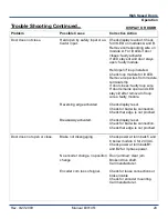
Страница 21: ...t LED Remove loop wires from module terminal strip If door closes faulty loop wire If door remains open and LED stays lit after removal of loop wires faulty module Check display reset Check for bad wire connection Check that edge is not pinched Check display reset Check for bad wire connection Check that edge is not pinched Door does not open or close Brake not disengaging No encoder change no pos...

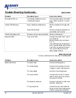
Страница 22: ... Remove wires from terminal 1 2 3 4 If 24 VDC present at terminal 1 and 4 isolate faulty light curtain If 24 VDC not present at termi nal 1 and 4 after removal of wires faulty module Motor Drive Fault To clear a fault press the stop key or cycle power Problem Possible Cause Corrective Action Motor drive fault F3 power loss F4 undervoltage F5 overvoltage F6 motor stalled F8 heatsink overheat F13 gr...

Страница 23: ...phase U to ground F39 phase V to ground F40 phase W to ground F41 phase UV short F42 phase UW short F43 phase VW short F70 power unit Check wiring between drive and motor Check motor grounded phase Contact manufacturer Check the motor and drive out put terminal wiring for shorted condition Contact manufacturer Recycle power If fault does not clear call manufacturer ...

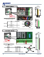
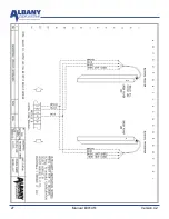
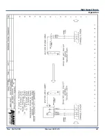
Страница 24: ... CONDUIT SEPARATE FOIL SHIELD SEPARATE FOIL SHIELD BRAKE WIRES WIRE STRIP GAUGE 8 6 NOTE TO CHANGE DIRECTION OF MOTOR ROTATION SWITCH T1 AND T2 MG MG MG T2 T1 T3 B1 B2 ENCODER WIRING DRILL ONLY INTO BOTTOM OF BOX USE MINIMUM CONDUIT LOW VOLTAGE CONDUIT ENCODER SAFETY ACTIVATION TB2 TB1 TB3 TB4 TB1 4 WIRE STRIP GAUGE ...

Страница 25: ...1 3 4 5 6 MODULE A 2 TB2 MODULE D LOOP DETECTOR 1 3 4 5 6 2 TB3 TB4 N H TOP 3 TERMINALS NEXT 5 TERMINALS H HERKULES MOTION SENSOR 1 3 4 5 6 MODULE A 2 TB3 GREEN BROWN PINK N WHITE GRAY RED Connect GRAY for Person Detection Connect RED for Vehicle Detection optional H FALCON MOTION SENSOR 1 3 4 5 6 MODULE A 2 TB3 RED WHITE N BLACK GREEN GRAY BLACK H RED N H GRAY ...

Страница 26: ...25 Manual 001451 Version 4 2 ...

Страница 27: ...Rev 9 27 2009 Manual 001451 26 Operation High Speed Doors ...

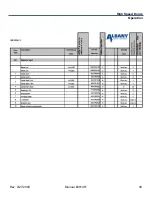
Страница 28: ...27 Manual 001451 Version 4 2 ...

Страница 29: ...Rev 9 27 2009 Manual 001451 28 Operation High Speed Doors ...

Страница 30: ... 6 Test the system Thoroughly test the system to determine if all sensors switches are functioning properly Make sure you can answer yes to the following questions Does the door reverse when the reversing edge is tripped upon closing If you cannot answer yes to all the above questions check all wiring connections and ensure the RFID is set to the same number that is labeled on the wireless bottom ...

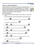
Страница 31: ...nd setup details 1 Press and hold until LIMIT SETUP is shown on the display Press 2 CLOSED LIMIT should be displayed Press 3 Use and or to bring the door to the full closed position Press 4 Press FULL OPEN LIMIT should be displayed Press 5 Use and or to bring the door to the full open position Press 6 Press PARTIAL OPEN LIMIT should be displayed Press 7 Use and or to bring the door to the partial ...

Страница 32: ...DOOR READY is displayed The Open and Partial Limits are all relative to the Closed Limit If the Closed Limit is reset to a different position all other limit set tings will change relative to the new Closed Limit setting SETTING TIMERS 1 Press and hold until LIMIT SETUP is shown on the display Press 2 Press until SET TIMERS is shown Press Use and or to cycle through the available options Press to ...

Страница 33: ... cal brake is utilized catching the bottom slat for a controlled deceleration This addendum shows how to reset the system to get your door operational Prior to resetting the brake you must lower the door to the open position Follow electrical instructions for lowering process Notice Inspect the door for damage prior to putting it back in service Repair door where necessary Failure to perform inspe...

Страница 34: ...rews Fig 3 so that you can move the yoke up and down easily Fig 3 Clamp Fig 4 Yoke at bottom position Move the yoke to the bottom of the clamp and retighten clamp Rotate yoke rest to a horizontal position and snap yoke into pocket Reset door limits Your door is now ready to go back into service ...

Страница 35: ...n the sensor relay and jog the door down using the Emergency Jog Down button on the face of the C Module 4 Once the door has been lowered below the normal open position stop 5 Reset the door limits as follows 1 Press and hold until LIMIT SETUP is shown on the display Press 2 CLOSED LIMIT should be displayed Press 3 Use and or to bring the door to the full closed position Press 4 Press FULL OPEN LI...

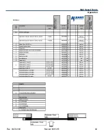
Страница 36: ...35 Manual 001451 Version 4 2 ...

Страница 37: ...Rev 9 27 2009 Manual 001451 36 Operation High Speed Doors ...

Страница 38: ...37 Manual 001451 Version 4 2 ...

Страница 39: ...Rev 9 27 2009 Manual 001451 38 Operation High Speed Doors ...

Страница 40: ...39 Manual 001451 Version 4 2 ...

Страница 41: ...Rev 9 27 2009 Manual 001451 40 Operation High Speed Doors ...

Страница 42: ...41 Manual 001451 Version 4 2 ...

Страница 43: ...Rev 9 27 2009 Manual 001451 42 Operation High Speed Doors ...

Страница 44: ...1080 Maritime Drive Port Washington WI 53074 Phone 262 268 9885 Fax 262 268 9895 albanydoors com ...

Отзывы: