Copyright © 2012 Alarm.com
|
www.alarm.com
|
v2.0
2
NetworX CDMA Module
|
Installation Guide
•
Locate the module near an outside wall, preferably on an upper level.
•
Leave 12 to 18 in. (30 to 45 cm) of open space above the module for the
antenna.
•
For homes or businesses located in canyons or with hills nearby, it is
necessary to place the antenna higher in the building.
Mounting
To mount the module, do the following:
1)
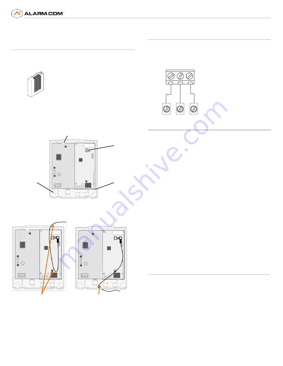
Press down on the top of the enclosure cover (Figure 2) and set it aside.
Figure 2: Enclosure Cover
2)
Snap the antenna onto the antenna connector (See
Figure 3).
To
connect the antenna, place one of your thumbs or fingers behind the
antenna connector.
With your other hand, press the end of the micro-
miniature coaxial connector into the antenna connector until you
head a slight click.
Figure 3: Antenna connector and mounting holes
3)
To avoid placing unnecessary strain on the antenna connector, which
can damage the module, use either of the following orientations
shown in
Figure 4.
Figure 4: Antenna wire orientation
4)
Place the module back plate on the wall at the desired mounting location,
check for level, and mark the three mounting holes and the wire access
area (Figure 3). Be sure to leave at least 12 to 18 in. (30 to 45 cm) above
the back plate for the antenna.
5)
Set the back plate aside and drill holes at the mounting and wire access
area locations.
6)
Use wall anchors where studs are not present and secure the back plate to
the wall with the enclosed screws.
CAUTION:
You must be free of static electricity before handling electronic
components. Touch a grounded metal surface before touching the board.
Wiring
To wire the module to the panel, do the following:
1)
Remove panel AC Power and disconnect the backup battery.
2)
Wire the module to the panel POS, COM and DATA terminals (as shown in
Figure 5
).
Figure 5: Wiring Terminals
Power Up
To power up the module and panel and start communication between them,
do the following:
1)
Verify that all wiring between the panel and module is correct.
2)
Connect the backup battery and restore AC power to the panel.
Note:
Whenever any module is added or changed, you must remove panel
power and reapply it for the panel and module to communicate
successfully.
3)
Verify that radio status LED 1 is not flashing any errors (see
Radio Status
LEDs
on page 3). Also, verify that LED 4 is flashing a signal level of two or
higher. Otherwise, relocate the module. If LED 1 and LED 4 are not
flashing, and LED 2 and LED 3 are flashing together, the module is in
PowerSave mode and the battery needs to be charged.
4)
Perform a manual phone test by pressing
*44
while the system is
disarmed
(Make sure that panel’s Location 37, Segment 2, Bit 7 is set).
Note:
if Location 37, Segment 2, Bit 6 is set, performing the phone test
will trigger the local siren. To avoid triggering the siren when
performing the phone test, make sure Bit 6 is OFF.
The panel will not show any indication that the phone test signal has been
sent. You can check the radio status LEDs L3 and L4: L4 should be blinking on
for 2 seconds and off for 2 seconds. L3 will blink once briefly as soon as you
press *44. If the account is reporting to a Central Station, wait for a minute
and check with the Central Station to see if the phone test signal was
received correctly. The phone test is also used by Alarm.com to set the
module's parameters the first time the module is powered up. It ensures that
Alarm.com will receive the sensors list and any other information required
for proper signaling.
Enrolling the Module
The NetworX control panels have the ability to automatically find and store
in memory the presence of all keypads, zone expanders, wireless receivers,
output modules, and any other device on the keypad bus. This allows these
devices to be supervised by the control panel. To enroll the devices, enter
Program Mode using the procedure outlined in the control panel installation
manual. When you exit Program Mode, the control panel will automatically
enroll the devices. The enrolling process takes about 12 seconds, during
which time the “Service” LED will illuminate. User codes will not be accepted
during the enrolling process. Once a module is enrolled, if it is not detected
by the control, the “Service” LED will illuminate. When initially powering up,
the control panel automatically performs the device enrollment process.
Press down
here
POS COM DATA
Gateway
Panel
KP POS KP COM KP DATA
Mounting Hole
Mounting Hole
Mounting Hole
Antenna Connector
Loop the wire and feed
it back through top
Feed the wire through
the bottom of the case


