


5
FOR
NEW
INSTALLATIONS:
Refer to the program-
ming manual (WI2258 or WI2264) for specific instruc-
tions for "First Time Startup" and "Change Factory
Master Code" before connecting the battery.
The lock must be powered up as instructed (and have
its factory Master Code changed) or erratic lock be-
havior can result.
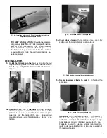
INSTALL LOCK
5. Install the DL lock onto the door
by aligning the four
tapped mounting holes in the back of the DL lock with the
four "through-bolting" holes that were drilled in the door in
step two.
5a. Secure the DL lock to the door
with four through-
door mounting screws and two door plates. Place a door
plate on top of a pair of mounting holes and
loosely
se-
cure lock from the inside of the door. Snug all four
mounting screws before final tightening.
Do not over-
tighten.
5b. Cover door plates
with decorative plate covers by
sliding them from top to bottom on door plates.
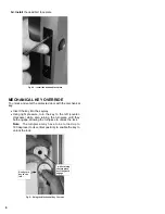
5c. Secure interface cylinder to lock
by tightening the
set screw.
Important!
If the interface cylinder is not parallel to
the door after tightening the set screw, then you must
verify that the original Adams Rite
®
lock body was origi-
nally installed correctly (installed square to the door).
Failure to ensure the interface cylinder is installed cor-
rectly could cause lock binding or improper operation of
the lock mechanism.
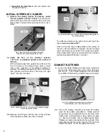
Fig. 4a: Install the battery pack: Push all wires inside the battery
compartment and slide plate back on.
Fig. 5a: Secure lock to door -- loosely at first
Door plate
Fig. 5b: Slide down to install decorative plate covers
Fig. 5c: Secure interface cylinder to lock
Fig. 5: Install the DL lock onto the door
Содержание Networx DL1325NW
Страница 7: ...7 This page intentionally left blank...


