


4
Reposition the template
as often as needed until
it is placed correctly.
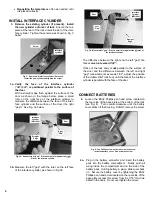
INSTALL INTERFACE CYLINDER
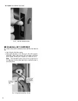
3. Remove the existing cylinder (if present). Install
the new cylinder onto rear of lock
. Ensure the tail-
piece at the rear of the lock enters the slot of the inter-
face cylinder. Tighten the set screw as shown in Fig. 3
below.
3a.
Verify the face of the interface cylinder
("HW1824")
is positioned parallel to the surface of
the door.
With a straight edge flush against the surface of the
door as shown in the image below, place a small
ruler on the right face of the interface cylinder to
measure the distance between the face of the inter-
face cylinder and the surface of the door (the right
"gap"). See Fig. 3a below.
3b.
Measure the left "gap" with the ruler on the left face
of the interface cylinder, as shown in Fig 3b.
The difference between the right and the left "gap" dis-
tances
must not exceed 1/32".
If face of the lock body is
not
parallel to the surface of
the door and the difference between the left and right
"gap" measurements exceeds 1/32", adjust the position
of the
Adams Rite
®
lock body until the face of the interface
cylinder is parallel with the face of the door.
CONNECT BATTERIES
4.
Loosen
the #8-32 Phillips pan head screw located on
the rear side of the base plate at the bottom of the lock
(see Fig. 4). Turn counter-clockwise until the battery
cover slides off the housing. Do NOT remove the screw.
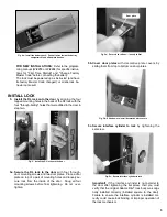
4a.
Plug in the battery connector and insert the battery
pack into the battery compartment. Neatly push all
wiring inside the compartment and on the side of the
battery pack.
Holding battery in place
, slide cover back
on. Secure the battery cover by tightening the #8-32
Phillips pan head screw located on the rear side of the
base plate (access this screw from the 7/16" thru-hole
drilled in the door).
Do not over tighten the screw
.
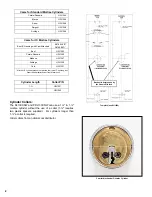
Fig. 3a: Measure right "gap": Place a small ruler against the right
side of the interface cylinder.
Straight
Edge
Interface
Cylinder
(HW1824)
Right
"Gap"
Door
Fig. 3b: Measure left "gap": Place a small ruler against the left side of
the interface cylinder.
Straight
Edge
Left
"Gap"
Door
Interface
Cylinder
(HW1824)
Fig. 3: Remove old interface cylinder (if present).
Install the new cylinder and tighten the screw.
Interface
cylinder
Screw
Fig. 4: The Phillips screw on the rear side locks or un-
locks the battery cover.
Do not remove screw
.
Содержание Networx DL1325NW
Страница 7: ...7 This page intentionally left blank...


