


15
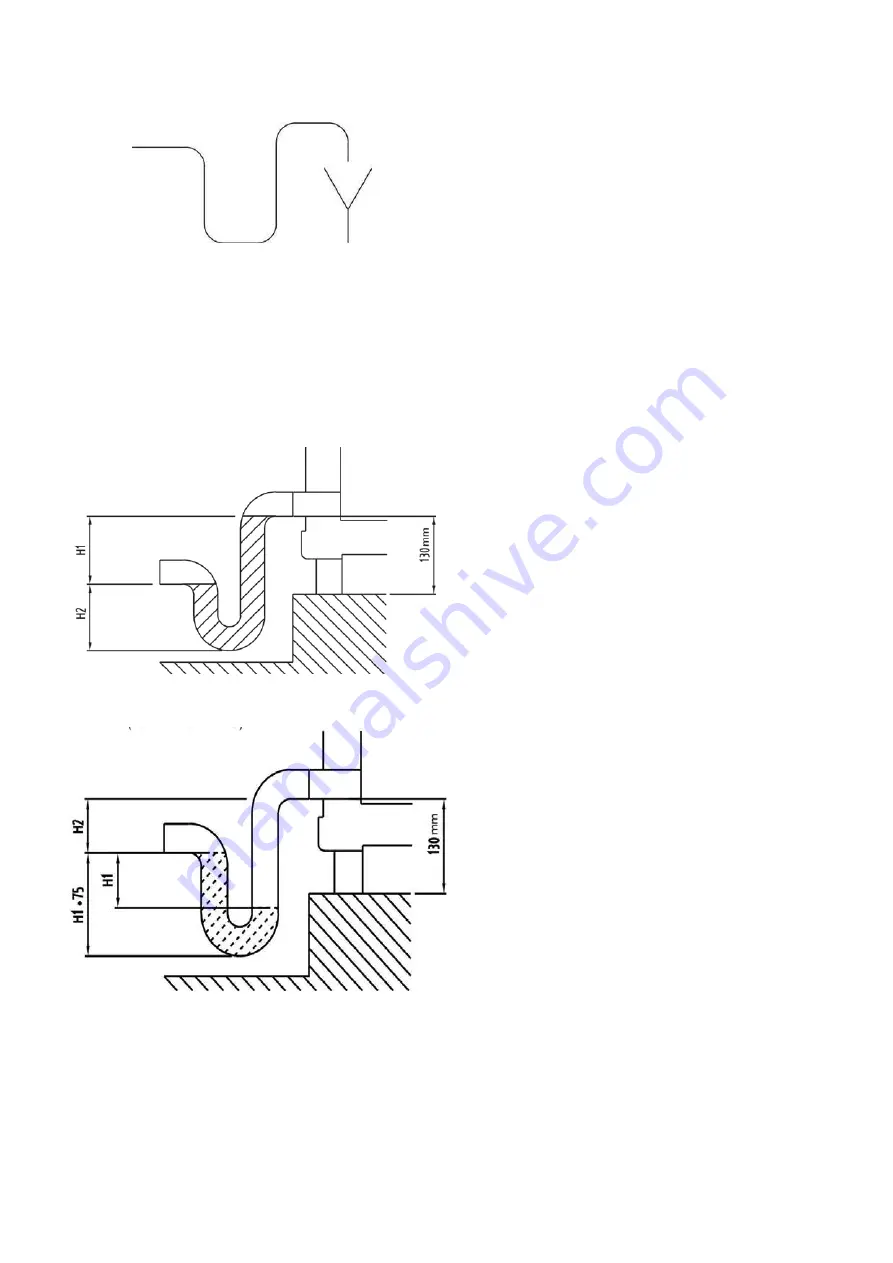
Positive pressure:
H1 = >maximum positive pressure in the cooler section (in mm WG) + 50 mm
H2 = 50 mm
Pressure in kPa (100 Pa = 10 mm WG)
•
Check if the droplet eliminator after the cooler has
been correctly installed.
•
Check if fins have been bent during transport.
•
Correctly straighten the fins.
•
The fins will only work correctly after several days in
dehumidification mode.
•
Start-up the cooling coil by opening the shut-off
valves. After several days of cooling operation check
the condensate drain and operation of the plastic
siphon.
•
If necessary clean the siphon.
•
City water can be used for water coils without any
conditioning.
4.7 - Heat recovery wheel
•
Ensure that the heat exchanger face area is not
damaged.
• Check that the wheel is rotating in the correct
direction.This is indicated by an arrow on the casing.
• Check if the wheel seals are fitting correctly.
• Check if belt tension is correct.
• Check if the motor and the rotation monitor have been
correctly connected (5 mm play between sensor and
detection point on the wheel).
• Ensure that the rotor speed has been correctly set.
The 39SQ condensation rotor must have a maximum
speed of 10 min-1; a sorption rotor must have a
maximum speed of 20 min-1. Refer to the user manual
for the heat recovery wheel controller.
• If the air intake temperature is below -15 °C, a pre-
heater is recommended for the heat recovery wheel to
prevent freezing.
4.6 - DX-coils
•
The DX-coils are supplied without refrigerant.
•
The coils must never be pressurised with water. They
must be sealed and pressurised with a gaseous
medium to prevent pollution of the coil.
•
A qualified person should charge the coil and the rest
of the system with a sufficient amount of the refrigerant
specified in the technical specifications.
•
When connecting the DX-coil to the compressor/
condensing unit always follow the supplier
specifications and the instructions of the qualified
personnel.
•
It is not recommended to connect several DX-coils to
one compressor/condensing unit.
•
It is best to use an infinitely variable controller for the
compressor / condensing unit. If the condensing unit
has infinitely variable control, one of the temperature
controls in the controller can be selected.
•
If the condensing unit does not have infinitely variable
control, set the AHU control for supply air temperature
control, and connect the DX entering temperature
sensor instead of the supply air sensor. The desired
(room) temperature must then be controlled by a
separate controller at the condensing unit.
If a changeover coil is supplied by a heat pump, the
installation must be designed to compensate for the
required heat during the system heat pump defrost cycle
and the heat cannot be drawn from the supply air.
Otherwise the supply air temperature cannot be achieved.
During the heat pump defrost cycle it must be possible to
add so much heat into the system that the desired entering
temperature (heater design capacity) as well as the
required heat for heat pump defrosting can be guaranteed.
AHU with control
To ensure that the correct control strategy for an AHU with
DX-coil can be selected, there is a temperature sensor on
the intake side of the DX-coil. If a heater is placed directly
before the DX-coil, this sensor is only accessible, if an
inspection section is installed between the two coils.
WARNING:
AVOID SPILLING liquid refrigerant on skin or getting it into
the eyes.
USE SAFETY GOGGLES. Wash any spills from the skin
with soap and water. If liquid refrigerant enters the eyes,
IMMEDIATELY FLUSH EYES with water and consult a
physician.
Fill siphon with water, if the fan is switched off.
Negative pressure:
H1 = maximum negative pressure in the cooler section (in mm WG) + 50 mm
H2 = >1/2 x H1
•
Check that the (negative or positive) pressure
corresponds to the siphon type installed.
•
The outlet of the siphon trap connected to the drain
must not be under pressure.
•
It is not recommended to connect a siphon in a
negative pressure section and a siphon in a positive
pressure section via a manifold that is not under
pressure to the drain. Instead two separate manifolds
should be used.
•
If the field-prepared siphon is used, follow the
instructions in the drawing below.


