


HM135/HM435 Programmer software guide
Preliminary version
Page
9
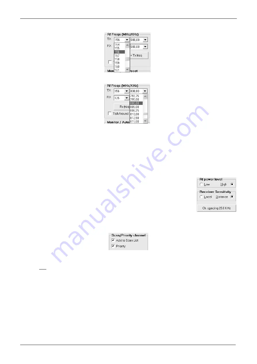
3) Go to the
Rf Freqs (MHz/KHz)
area and select the TX frequency in MHz in the upper box
TX
by clicking its left drag down button, then
click the hundreds MHz you require (e.g.
156
for 156 MHz)
4) Select now the decimal TX frequency in KHz by clicking the right drag down button, then point the decimal frequency you need (e.g.
800,00
will select 156,800.00 MHz)
As soon as you have clicked the right drag down button, you can quickly program to the hundred KHz you need by pressing the related
number buttons in your PC’s keyboard. E.g. to quickly program
825,00
KHz, just type the keys
8 2 5
in your PC’s keyboard, then press
the
Enter
key in order to set the said decimal frequency.
5) Now that you have selected the whole TX frequency, you have three choices:
If you are programming a simplex channel
(same RX and TX frequency), click the
Rx freq = Tx freq
button: The RX frequency
will be immediately set to the just programmed TX one. After you did that, go directly to step 7) (i.e. skip the next step)
If you are programming a duplex channel
(RX frequency different than the TX one), go to
RX
box and set up the hundreds MHz
and the decimal RX frequency performing the same operation described in steps 2) and 4)
6) If you have selected a duplex channel, the
TalkAround
checkbox will be available in the
Rf Freqs (MHz/KHz)
area. If you tick it, the Talk
Around feature will be automatically set on as default on the selected channel.
The Talk Around feature is the possibility to communicate in simplex mode at the output frequency of the
repeater (your RX frequency) in case the said repeater is faulty.
7) To select the TX output power go to
RF power level
area and select either the
Low
or
High
radio button for
that channel depending on your choice (in the example we have chosen
High
).
8) To change the default receiver’s sensitivity go to the
Receiver sensitivity
area and select either the
Local
or
Distance
radio button for that channel depending on your needs. For regular applications, we recommend
to use the maximum sensitivity by keeping the default
Distance
setting.
9) Select the channel bandwidth (either
25
or
12.5
KHz) by clicking the
Ch. spacing
button until you’ll see your
choice on it (the figure shows 12.5 KHz)
10) If you want to add the channel to the scan list, go to
Scan/Priority channel
area and tick the
Add to Scan List
checkbox. In this case,
the
Priority
checkbox will be immediately available. Tick it if you want to designate the channel as priority one.
Obviously, you can designate only one priority channel. If you already did that with another channel, a message will warn you until you
won’t remove the checkbox from the former priority channel
If you don’t tick the priority checkbox in all the programmed channels, the user has the possibility to define the priority channel as
described in the user’s manual (if this function has been enabled as later explained)
11) You have now programmed the basic channel specifications in the transceiver. However, depending on your customer’s requirements,
you may need to program other channels and/or add CTCSS/DCS and/or Selective Call facilities and/or other options. You have three
options:
If you need to program the basic parameters of additional channels
, go to step 12). CTCSS/DCS, Selective Calls and other
options will be further added as we’ll describe.
If you already have programmed the basic parameters of all the needed channels, but you still need to add the CTCSS/DCS
and/or Selective Call facilities and/or other options,
go to the appropriate paragraph/chapter: 3.8 for CTCSS/DCS and/or
Chapters 4 & 5 (the whole chapters) for Selective call and/or chapters 4 & 6 (the whole chapters) for other options
If you already have programmed the basic parameters of all the needed channels and you don’t need to add any CTCSS/DCS
and/or Selective Call facilities and/or other options
(i.e. you have complete the programming), go to chapter 7.1 in order to
transfer the program to the unit.
Содержание HM135
Страница 14: ...ALAN HM 135 TEST POINTS AND PCB LAYOUTS...
Страница 16: ...p d f M a c h i n e b y B r o a d G u n S o f t w a r e...
Страница 17: ...p d f M a c h i n e b y B r o a d G u n S o f t w a r e...
Страница 18: ...p d f M a c h i n e b y B r o a d G u n S o f t w a r e...
Страница 19: ...p d f M a c h i n e b y B r o a d G u n S o f t w a r e...
Страница 20: ...p d f M a c h i n e b y B r o a d G u n S o f t w a r e...
Страница 21: ...p d f M a c h i n e b y B r o a d G u n S o f t w a r e...
Страница 22: ...p d f M a c h i n e b y B r o a d G u n S o f t w a r e...
Страница 23: ...p d f M a c h i n e b y B r o a d G u n S o f t w a r e...
Страница 24: ...p d f M a c h i n e b y B r o a d G u n S o f t w a r e...
Страница 25: ...p d f M a c h i n e b y B r o a d G u n S o f t w a r e...
Страница 26: ...ALAN HM 135 ELECTRICAL DIAGRAMS...
Страница 27: ...HM135_HEAD_FEB_14_2004 SCH p d f M a c h i n e b y B r o a d G u n S o f t w a r e...
Страница 28: ...12 13 14 D 5 6 7 B 10 8 9 C p d f M a c h i n e b y B r o a d G u n S o f t w a r e...
Страница 29: ...5 6 7 B 12 13 14 D 1 2 3 A 1 2 3 A 10 8 9 C p d f M a c h i n e b y B r o a d G u n S o f t w a r e...
Страница 31: ...10 8 9 C 5 6 7 B 1 2 3 A 5 6 7 B 12 13 14 D p d f M a c h i n e b y B r o a d G u n S o f t w a r e...
Страница 32: ...p d f M a c h i n e b y B r o a d G u n S o f t w a r e...
Страница 33: ...1 2 3 4 8 A p d f M a c h i n e b y B r o a d G u n S o f t w a r e...
Страница 34: ...5 6 7 B p d f M a c h i n e b y B r o a d G u n S o f t w a r e...
Страница 35: ...5 6 7 B 10 8 9 C 1 2 3 A 12 13 14 D p d f M a c h i n e b y B r o a d G u n S o f t w a r e...
Страница 36: ...p d f M a c h i n e b y B r o a d G u n S o f t w a r e...
Страница 37: ...ALAN HM 135 EXPLODED VIEW AND PART LIST...
Страница 38: ...ALAN HM 135 PROGRAMMING MANUAL...


