background image

Repair Manual 1 


1

Version 1.00

Version 1.00

Welding can create heat stress, which may cause the impeller to bre-
ak when used. This is why the manufacturer is not responsible for the 
breaking down of a repaired impeller.

Impeller material: GTp10 

Filler metal: EL-CuSn7 (ESAB OK 94.24).

If the impeller has been repaired with filler metal, it is to be machined 

if necessary and it is imperative that it be balanced!

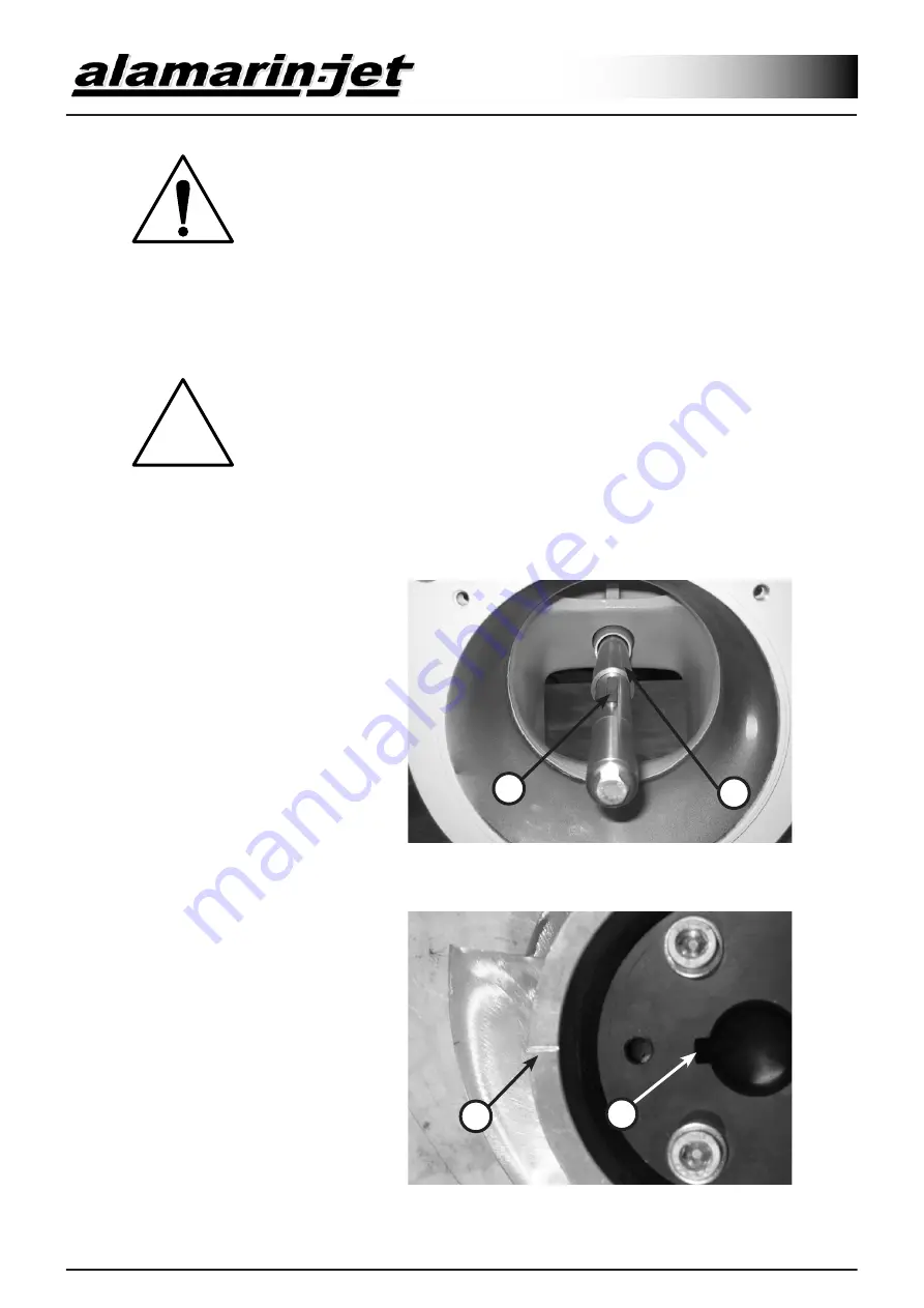
3.3. Installation

Screw the adjuster sleeve (A) 
and the possible additional ring 
on the shaft. The sleeve has a 
left hand thread, but the additio-
nal ring is unthreaded.

Place the wedge (B) in its groo-

ve (figure 3.3-1).

Figure 3.3-1

A

B

The place for the wedge groo-
ve (A) on the mounting cone 
is marked on the impeller with 
a line. Set the cone so that the 
wedge groove is aligned with 

the line (B) as in figure 3.3-2.

Figure 3.3-2

B

A

Содержание Jet-160

Страница 1: ......

Страница 2: ...s the following jet propulsion models Jet 160 Jet 180 Jet 185 If the given information is type specific this will be expressed in the text Clarifying figures will be used in this manual NOTE the text...

Страница 3: ...11 2 1 2 Assembly and Installation 13 2 1 2 1 Jet 160 13 2 1 2 2 Jet 180 185 14 2 2 Rear End Bearing Disassembly and Assembly 15 3 Impeller 17 3 1 Detachment 17 3 2 Repair 17 3 3 Installation 18 3 4 T...

Страница 4: ...eflector Control 27 7 1 Installation Instructions 28 7 2 Adjustment Instructions 29 APPENDIXES Appendix 1 Recommended Greases and Tightening Torgues 30 Appendix 2 Impeller Dimensions 31 Appendix 3 Ord...

Страница 5: ...s attached to the flywheel to a coupling flange installed by the engine manufacturer or to the gearbox There can be an adapter flange between the joint and the engine with which the engine and shaft h...

Страница 6: ...running The cardan shaft has been installed similarly to the constant velocity shaft Adapter flan ges are used sometimes because the shaft engine and jet propulsion unit flanges are not always compat...

Страница 7: ...est of these are SAE 1310 VNA 10 If necessary there is an adapter between the coupling flange and the transmission shaft which enables fastening Removing The coupling flange is tightened on the conica...

Страница 8: ...1 Front Bearing 2 1 1 1 Jet 160 The bearing housing is fixed in the casting Only the support bearing housing is remova ble Before the shaft can be disassembled the reversing deflector the steering no...

Страница 9: ...er Figure 2 1 1 1 3 The bearing figure 2 1 1 1 4 consists of a thrust bearing that receives the pure axial force A and an angular ball bearing that carries radial loads C The plate B between the beari...

Страница 10: ...ure 2 1 1 1 6 There is a needle bearing in the support bearing housing which carries radial forces There is a shaft seal behind the bearing and a safety ring in front of it which stops the bearing fro...

Страница 11: ...t bearing housing figures 2 1 1 2 1 and 2 1 1 2 2 The actual bearing housing is attached to the body with sealing and adhesive compound It is not necessary to remove it unless it is dama ged Figure 2...

Страница 12: ...ter race of the bearing See figure 2 1 1 2 5 A Figure 2 1 1 2 5 B To remove the bearing remove the safety ring and push the bearing to the direction of the safety ring groove B See figure 2 1 1 2 5 Fi...

Страница 13: ...y and Installation 2 1 2 1 Jet 160 Make sure that the bearing housing and the support bearing housing are absolu tely clean Push the thrust bearing on the shaft The thrust bearing consists of three pa...

Страница 14: ...seal is being pushed into place the lips must point away from the installer WARNING If the shaft seal is installed backwards water gets into the bearing housing Also make sure that the ring that suppo...

Страница 15: ...g housing is glued to the stator It is possible to remove the housing When changing the rear end bearings it is recommended that the whole housing is replaced When only changing the seals they should...

Страница 16: ...hesive manufacturer s recommendations There is a replaceable wear sleeve figure 2 2 4 A at the rear end of the shaft It is re moved by first opening the bolt figure 2 2 4 B and removing the locking pl...

Страница 17: ...olt out of the threa ded hole and spin it loosely into the free hole B i e back in its original place Pull the impeller off the shaft Figure 3 1 1 A B The plastic cone may still sit tightly on the sha...

Страница 18: ...ith filler metal it is to be machined if necessary and it is imperative that it be balanced 3 3 Installation Screw the adjuster sleeve A and the possible additional ring on the shaft The sleeve has a...

Страница 19: ...r recedes slightly out wards in the cone hole which causes the gap to adjust to the correct size automatically After this tighten the impeller adjus ter sleeve as tight as manually possible See figure...

Страница 20: ...ction 6 1 3 Attach the loop joint on the reversing deflector to the lever at the end of the control shaft Section 4 1 3 Attach the loop joint on the steering nozzle to the lever at the end of the cont...

Страница 21: ...ht ruler against the rear edge of the cone as in dicated in figure 3 4 3 and me asure the distance from the rear edge of the cone to the rear edge of the impeller This measure is about 2 mm at the sma...

Страница 22: ...control shaft of the reversing deflector is attached to the reversing deflector with loop joints A Remove the loop at the shaft side The deflector is pivoted to the stator with acid proof sleeves and...

Страница 23: ...deflector and other casting parts AlSi7Mg Filler metal AlMg5 4 1 3 Installation The reversing deflector is installed in a reverse order compared to removing Attach the deflector first to the stator w...

Страница 24: ...ote of the order of the washers The free threading on the stator resists screw rotation and in addition thread locking has been used in installation so the screw will not open by hand Figure 5 1 1 1 B...

Страница 25: ...ontrol shaft Use thread locking compound The tightening torque of the screws is 50Nm 5 2 Steering Shafts As the control shaft the steering shaft goes through two points of support or lead throughs one...

Страница 26: ...gure 6 1 1 1 Carefully crank the stator loose using a screwdriver figure 6 1 1 2 Figure 6 1 1 1 Figure 6 1 1 2 6 1 2 Detachment as Whole Remove the reversing deflector and steering nozzle loop joint a...

Страница 27: ...n tighten them evenly to a tightening torque of 50Nm A small gap is left between the stator and the body because the end of the propeller duct extends outer than the other parts and corresponds with t...

Страница 28: ...the setting dimension of 413 mm figure SE 01 The spindle motor can point perpendicularly either to the right or left Note that the spindle motor is locked with steel wire to prevent the spindle from r...

Страница 29: ...or back to centre position with the ZERO trim Test the suitability of the area again with the STICK If the area is still too wide repeat the procedure above Instead if the area is too small repeat the...

Страница 30: ...s 2 operating temperature range 25 130 C continuous operating temperature min 75 C The following grease brands are recommended as an example W rth Multi Purpose Grease III FAG Multi2 FAG Load 220 Mobi...

Страница 31: ...Version 1 00 31 APPENDIXES Repair Manual 1 Appendix 2 IMPELLER DIMENSIONS...

Страница 32: ...etrol diesel _______________________________________________ Power kW hv ________________________________________________________ Number of cylinders __________________________________________________...

Страница 33: ...Version 1 00 33 APPENDIXES Repair Manual 1 Appendix 4 SE 01...

Страница 34: ...APPENDIXES Repair Manual 1 34 Version 1 00 Version 1 00 Appendix 5 SE 02...

Страница 35: ...ploded Views When delivering this manual in paper form the manufacturer has added to the following pages the exploded views of the propulsion unit model with which the manual is delive red In the elec...

Отзывы: