background image

English

Detector assembly

The detector should be installed in an area where the highest 
amount of gas may concentrate, near places where gas leaks 
could  start  and  accessible  for  maintenance  work.  It  is  also 

advisable to place it away from transit areas or areas where it could be 
accidentally knocked.
Different types of gas can have different densities, and this means that 
leaks could concentrate in the lowest part of the room or near the roof. 
Take this into account when deciding on the height of the detector.
It  is  advisable  to  install  the  freon  detectors  around  20  cm  from  the 
ground, with an free distance around them of some 50 cm.

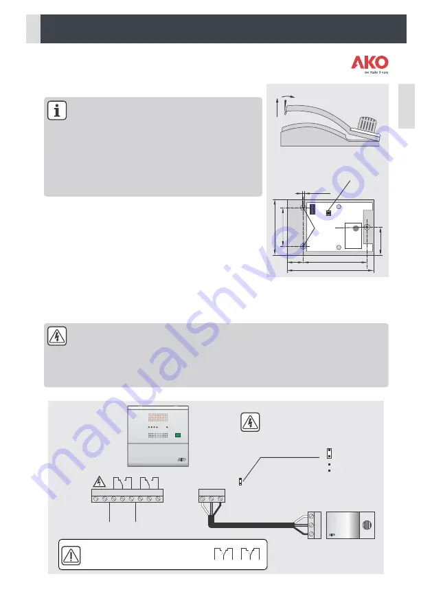
- Remove the detector's cover (Fig. 4).
- Drill  the  hole  for  the  glands  needed  for  the  cable  entry  following  the 

pre-stamped centres on the bottom or top of the base.

- Drill 3 holes on the wall following the fixing holes. (Fig. 5).
- Fasten the gland onto the base.
- Insert  the  3  plugs  through  the  base,  into  the  3  holes  on  the 

wall and tighten.

- Insert  the  cables  into  the  gland  and  connect  them  according  to  the 

wiring diagram.

- Adjust the alarm/pre-alarm delays using the delay switch (See page 11)
- Insert the cover and gently press it until you hear a “click”.

Wiring

Always disconnect the power supply to do the wiring.
The power circuit should be equipped with a switch for its disconnection of at least 2 A, 230 V, situated 

near the appliance. The power supply cable should be H05VV-F or H05V-K type. The gauge will depend on local 

2

regulations, but should in no case be less than 1 mm . 
Cables for wiring the relay contact should have an adequate section depending on the unit to be connected.
AKO recommends the use of shielded cable for the wiring of the detectors.

Alarm 

Output

16A

16A

Pre-alarm 

Output

NC

NC

NO

NO

C

C

-

S

+

1

L

4

5

2

N

+

3

6

S

-

+12Vcc

Input

90-260 V~

50/60 Hz

GND

Signal

DETECTOR 1

Pre-alarm jumper

Always disconnect the power supply before 
changing the position of the jumper.

Max. 200 mts.

Without pre-alarm

With pre-alarm

Status of the relays in the case of 
a failure in the electricity supply.

16A

16A

1

4

5

2

3

6

Fastening 
holes

Delay switch

Fastening holes suitable for 
universal built-in housing

Press gently

168

125,5

35

92

60

41,5

Max. Ø 3,7

FIG. 4

FIG. 5

12

Содержание AKO-52201

Страница 1: ...rmanente Gas leak detection alarm for permanent connection Alarme de d tection de fuites de gaz pour connexion permanente Gasleck Detektionsalarm f r dauerhaften Anschluss Alarme de detec o de fugas d...

Страница 2: ...tas en su manual AKO Electromec nica no garantiza su funcionamiento en cualquier utilizaci n no prevista en dicho documento as como no se responsabilizar en ning n caso de los da os de cualquier tipo...

Страница 3: ...uraci n o almacenaje de frutas debido a que algunas frutas pueden emitir gases Salidas de humo localizadas en espacios confinados dioxido de carbono propano LPG o procedentes de motores generadores o...

Страница 4: ...enta los retardos Valor por defecto Retirar la tapa T del equipo Fig 1 Abrir el equipo y separar el frontal de la caja Fig 2 Realizar los taladros para los prensaestopas necesarios para entrada de los...

Страница 5: ...l prensaestopa y conectarlos seg n el esquema de conexionado Ajustar los retardos de alarma Pre alarma mediante el selector de retardo Ver p Insertar la tapa y presionar ligeramente hasta escuchar cli...

Страница 6: ...te alternativo Sin alimentaci n Off Off Off Off Off 1 4 5 2 3 6 A B C D E F 1 4 5 2 3 6 1 4 5 2 3 6 1 4 5 2 3 6 1 4 5 2 3 6 1 4 5 2 3 6 1 4 5 2 3 6 Concentraci n de GAS ppm t Nivel de pre alarma Nivel...

Страница 7: ...y ajustar el selector de retardo a Sin retardo Cerrar la tapa y volver a conectar la alimentaci n del equipo Esperar 5 minutos antes de efectuar la comprobaci n Iniciodelacomprobaci n AKO 52211 Tipo A...

Страница 8: ...P 40 Categor a de instalaci n II s EN 61010 1 Grado de poluci n II s EN 61010 1 Aislamiento doble entre alimentaci n circuito secundario y salida rel Potencia sonora 90 dB A a 1 metro Norma EMC EN 610...

Страница 9: ...does not guarantee its operation in any use not foreseen in this document and accepts no liability in the case of damage of any type which may result from incorrect use configuration installation or c...

Страница 10: ...Fruit ripening or storage rooms as some fruits can emit gases Smoke outlets located in confined spaces carbon dioxide propane LPG or from engines generators or motorised machinery fork lift trucks etc...

Страница 11: ...ut taking into account the delays Remove the cover T of the equipment Fig 1 Open the equipment and remove the front of the housing Fig 2 Drill the holes needed for the cable entry glands using the pre...

Страница 12: ...to the gland and connect them according to the wiring diagram Adjust the alarm pre alarm delays using the delay switch See page 11 Insert the cover and gently press it until you hear a click Wiring Al...

Страница 13: ...ve Without power supply Off Off Off Off Off 1 4 5 2 3 6 A B C D E F 1 4 5 2 3 6 1 4 5 2 3 6 1 4 5 2 3 6 1 4 5 2 3 6 1 4 5 2 3 6 1 4 5 2 3 6 GAS concentration ppm t Pre alarm level Alarm level A B B C...

Страница 14: ...ector s red indicator turns on permanently The alarm station emits a two tonesound Thealarmrelayactivates l The alarms disappear after 1 to 2 minutes The detector s red indicator turns off and the gre...

Страница 15: ...EN 61010 1 Pollution degree II s EN 61010 1 Double isolation between power supply secondary circuit and relay output Sound power 90 dB A at 1 metre EMC Standard EN 61000 Power supply 15 Vdc 3 Vdc Con...

Страница 16: ...ons d crites dans son manuel AKO Electromec nica ne garantit pas son fonctionnement dans les cas non pr vus dans ledit document et ne sera en aucun cas tenue responsable des dommages quels qu ils soie...

Страница 17: ...e de fruits puisque certains fruits peuvent mettre des gaz Sorties de fum e situ es dans des espaces confin s dioxyde de carbone propane LPG ou provenant de moteurs de g n rateurs ou de machines motor...

Страница 18: ...nt les alarmes et pr alarmes sans tenir compte des retards Retirer le couvercle T de l quipement Fig 1 Ouvrir l quipement et retirer la face avant du bo tier Fig 2 Percer les trous n cessaires pour le...

Страница 19: ...ns les 3 trous du mur Ins rer les c bles dans le presse toupe et les brancher selon le sch ma de connexion R gler les retards d alarme pr alarme gr ce au s lecteur de retard Voir page 18 Ins rer le co...

Страница 20: ...atif Sans alimentation Off Off Off Off Off 1 4 5 2 3 6 A B C D E F 1 4 5 2 3 6 1 4 5 2 3 6 1 4 5 2 3 6 1 4 5 2 3 6 1 4 5 2 3 6 1 4 5 2 3 6 Concentration de GAZ ppm t Niveau de pr alarme Niveau d alarm...

Страница 21: ...e du d tecteur et r glez le s lecteur de retard sur Sans retard l Fermez le couvercle et rebranchez l alimentation lectrique de l appareil Attendez 5 minutes avant de faire la v rification D butdelav...

Страница 22: ...40 Cat gorie d installation II s EN 61010 1 Niveau de pollution II s EN 61010 1 Isolation double entre alimentation circuit secondaire et sortie relais Puissance acoustiquea 90 dB A 1 m tre Norme EMC...

Страница 23: ...tie f r seine Funktionsweise bei irgendeiner Verwendung die in dem genannten Dokument nicht vorgesehen ist sowie keine Haftung f r Sch den die durch eine unsachgem e Verwendung Konfiguration Installat...

Страница 24: ...r K ltemitteln gearbeitet wird Reifungs oder Lagerungsbereiche f r Obst weil bestimmte Obstsorten Gase freisetzen k nnen Rauchabz ge in geschlossenen R umen Kohlendioxyd Propan LPG oder von Motoren St...

Страница 25: ...ten sofort an Die Abdeckung T vom Ger t abnehmen Abb 1 Das Ger t ffnen und die Frontplatte des Geh uses entfernen Abb 2 Die Bohrungen f r die Stopfbuchsen ausf hren die f r die Einf hrung der Kabel er...

Страница 26: ...anziehen Die Kabel durch die Stopfbuchse f hren und gem dem Schaltbild anschlie en Die Verz gerungszeiten f r Alarm Voralarm am Verz gerungsw hlschalter einstellen siehe Seite 25 Abdeckung ansetzen un...

Страница 27: ...rgung Aus Aus Aus Aus Aus 1 4 5 2 3 6 A B C D E F 1 4 5 2 3 6 1 4 5 2 3 6 1 4 5 2 3 6 1 4 5 2 3 6 1 4 5 2 3 6 1 4 5 2 3 6 GAS Konzentration ppm t Voralarm pegel Alarmpegel A B B C C C D D E E F F Wenn...

Страница 28: ...auf Das Alarmger t gibt einen Zweitonalarm aus Das Alarmrelais wird aktiviert l Nach 1 und 2 Minuten werden die Alarme aufgehoben Die rote Anzeige des Sensors erlischt und die gr ne Anzeigeblinktlang...

Страница 29: ...010 1 Verschmutzungsgrad II gem EN 61010 1 Doppelte Isolierung zwischen Stromversorgung Sekund rkreis und Relaisausgang Schall Leistung 90 dB A in 1 Meter EMV Norm EN 61000 Stromversorgung 15 Vdc 3 Vd...

Страница 30: ...lectromec nica n o garante o seu funcionamento em caso de utiliza o n o prevista no referido documento assim como n o se responsabilizar em caso algum por danos de qualquer tipo eventualmente provocad...

Страница 31: ...mento ou armazenamento de frutos j que alguns frutos podem libertar gases Exaustores de fumos localizadas em espa os confinados di xido de carbono propano LPG ou de motores geradores ou m quinas a mot...

Страница 32: ...orma imediata sem ter em conta os atrasos Retirar a tampa T do equipamento Fig 1 Abrir o equipamento e separar a parte frontal da caixa Fig 2 Efectuar as fura es para os prensa estopas necess rios par...

Страница 33: ...os cabos no prensa estopa e lig los segundo o esquema el ctrico Ajustar os atrasos de alarme pr alarme atrav s do selector de atraso Ver p g 32 Inserir a tampa e pressionar ligeiramente at ouvir um e...

Страница 34: ...cabos Ligado Ligado 3 sinais curtos a cada 2 minutos Intermitente alternativo Sem alimenta o Desligado Desligado Desligado Desligado Desligado 1 4 5 2 3 6 A B C D E F 1 4 5 2 3 6 1 4 5 2 3 6 1 4 5 2 3...

Страница 35: ...lho do detector apaga se e o indicador verdecome aapiscarlentamente Osrel sdoalarmeepr alarmes odesactivados Caso o pr alarme n o seja activado verifique se n o est desligado na central de alarme cons...

Страница 36: ...1 REV 03 2011 AKO ELECTROMEC NICA S A L Av Roquetes 30 38 08812 Sant Pere de Ribes Barcelona Espa a Tel 34 938 142 700 Fax 34 938 934 054 e mail ako ako com www ako com Apartado P O Box 5 08800 Vilano...

Отзывы: