background image

49

g

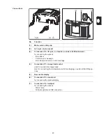
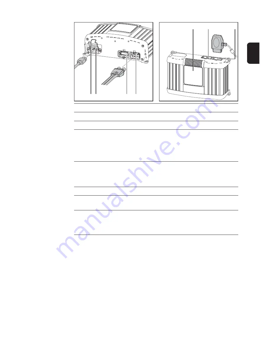
Connections

No.

Function

(1)

Mains cable safety clip

(2)

AC input - mains socket

(3)

Connection P2 - I/O port - no function, can be retrofitted however

for connecting the options:

-

Immobiliser

-

Common error message

-

Immobiliser and common error message

(4)

Connection P1 - charger lead socket

used to connect the charger lead

also for connecting the temperature-controlled charging or external Start/Stop op-
tions

(5)

Removable display

(6)

Connection P3 - visual port

for connecting the internal display

(7)

Connection P4 - multiport

for connecting the options:

-

Status lamp

-

Software update via USB connection

(1)(2)

(3)

(4)

(6)

(7)

(5)

Содержание vas 5900A

Страница 1: ...42 0410 1768 022010 D Batterieladesystem Bedienungsanleitung GB Battery charging system Operating instructions ...

Страница 2: ...0 ...

Страница 3: ...ätekonzept 9 Warnhinweise am Gerät 9 Inbetriebnahme 11 Sicherheit 11 Bestimmungsgemäße Verwendung 11 Netzanschluss 11 Sicherheitskonzept Schutzeinrichtungen serienmäßig 11 Bedienelemente und Anschlüsse 13 Allgemeines 13 Bedienpanel 13 Anstecken von Optionen 13 Anschlüsse 14 Abdeckungen für Anschlüsse und Optionen entfernen 15 Option Haltebügel und Option Zugentlastung für Ladekabel montieren 15 Op...

Страница 4: ...etzen 27 Betriebsart Netzteil Modus 28 Voraussetzungen 28 Netzteil Modus 28 Geräteeinstellungen 30 Allgemeine Information 30 Betriebsart Geräteeinstellungen anwählen 30 Konfiguration 30 Kennlinien 31 Sicherheit 31 Verfügbare Kennlinien 31 Fehlerdiagnose Fehlerbehebung 32 Sicherheit 32 Schutzeinrichtungen 32 Ladefehler 33 Technische Daten 35 Elektrische Daten Eingang 35 Elektrische Daten Ausgang 35...

Страница 5: ...dem Stand der Technik und den anerkannten sicherheits technischen Regeln gefertigt Dennoch drohen bei Fehlbedienung oder Miss brauch Gefahr für Leib und Leben des Bedieners oder Dritte das Gerät und andere Sachwerte des Betreibers die effiziente Arbeit mit dem Gerät Alle Personen die mit der Inbetriebnahme Bedienung Wartung und Instand haltung des Gerätes zu tun haben müssen entsprechend qualifizi...

Страница 6: ...ür hieraus entstandene Schäden haftet der Hersteller nicht Genaue Informationen über die zulässigen Umgebungsbedingungen entneh men Sie den technischen Daten im Beiblatt Geräte mit hoher Leistung können auf Grund ihrer Stromaufnahme die Ener giequalität des Netzes beeinflussen Das kann einige Gerätetypen betreffen in Form von Anschluss Beschränkungen Anforderungen hinsichtlich maximal zulässiger N...

Страница 7: ...offkonzentration unter 4 gewährleistet ist Während des Ladens einen Mindestabstand von 0 5 m 19 69 in zwi schen Batterie und Ladegerät einhalten Mögliche Zündquellen sowie Feuer und offenes Licht von der Batterie fernhalten Die Verbindung zur Batterie z B Ladeklemmen keinesfalls während des Ladevorganges abklemmen Entstehende Gase und Dämpfe keinesfalls einatmen Für ausreichend Frischluftzufuhr so...

Страница 8: ... einer Elektro Fachkraft auf Funktionstüchtigkeit des Schutzleiters überprüfen lassen Nicht voll funktionstüchtige Sicherheitseinrichtungen und Bauteile in nicht einwandfreiem Zustand vor dem Einschalten des Gerätes von einem auto risierten Fachbetrieb instandsetzen lassen Schutzeinrichtungen niemals umgehen oder außer Betrieb setzen Nach dem Einbau ist ein frei zugänglicher Netzstecker erforderli...

Страница 9: ...d gefertigt sind Ohne Genehmigung des Herstellers keine Veränderungen Ein oder Um bauten am Gerät vornehmen Die Gewährleistungszeit für das Gerät beträgt 2 Jahre ab Rechnungsdatum Der Hersteller übernimmt jedoch keine Gewährleistung wenn der Schaden auf eine oder mehrere der folgenden Ursachen zurückzuführen sind Nicht bestimmungsgemäße Verwendung des Gerätes Unsachgemäßes Montieren und Bedienen B...

Страница 10: ...her Richtli nie 2002 96 EG über Elektro und Elektronik Altgeräte und Umsetzung in na tionales Recht müssen verbrauchte Elektrowerkzeuge getrennt gesammelt und einer umweltgerechten Wiederverwertung zugeführt werden Stellen Sie sicher dass Sie Ihr gebrauchtes Gerät bei Ihrem Händler zurückgeben oder holen Sie Informationen über ein lokales autorisiertes Sammel und Entsor gungssystem ein Ein Ignorie...

Страница 11: ...stet Dafür steht eine Vielfalt von Optionen zur Verfü gung Eine Spannungsbegrenzung auf 14 4 V sorgt für optimalen Schutz der Fahrzeug Bordelektronik Warnhinweise am Gerät Das Ladegerät ist mit Sicherheitssymbolen am Leistungsschild ausgestattet Die Sicher heitssymbole dürfen weder entfernt noch übermalt werden Funktionen erst nach vollständigem Lesen der Bedienungsanleitung anwenden Mögliche Zünd...

Страница 12: ...10 Ausgediente Geräte nicht in den Hausmüll werfen sondern entsprechend den Sicherheitsvorschriften entsorgen ...

Страница 13: ...stecker bei Ihrer Geräteausführung nicht angebracht Netzkabel oder Netzstecker entsprechend den nationalen Normen montieren Sicherheitskon zept Schutzein richtungen serienmäßig Folgende Sicherheitsmerkmale zählen zum Lieferumfang der Active Inverter Spannungs und funkenfreie Klemmen schützen vor Explosionsgefährdung Der Verpolschutz verhindert eine Beschädigung oder Zerstörung des Ladegerätes WARN...

Страница 14: ...e Ladezeit Überwachung schützt effektiv vor Überladung und Zerstörung der Bat terie Dank der hohen Schutzart ergibt sich bei widrigen Bedingungen eine reduzierte Ver schmutzungsrate Davon profitiert die Zuverlässigkeit des Ladegerätes Übertemperaturschutz mittels Derating Reduktion des Ladestroms bei Anstieg der Temperatur über den Grenzbereich ...

Страница 15: ...ualisierungen können Funktionen an Ih rem Gerät verfügbar sein die in dieser Bedienungsanleitung nicht beschrieben sind oder umgekehrt Zudem können sich einzelne Abbildungen geringfügig von den Bedienelementen an Ihrem Gerät unterscheiden Die Funktionsweise dieser Bedienelemente ist jedoch identisch WARNUNG Fehlbedienung kann schwerwiegende Personen und Sachschä den verursachen Beschriebene Funkti...

Страница 16: ...error Wegfahrsperre und Sammelerror 4 Anschluss P1 Buchse Ladekabel zum Anschließen des Ladekabels zusätzlich zum Anschließen der Option temperaturgeführtes Laden oder externer Start Stop 5 Display abnehmbar 6 Anschluss P3 Visual Port zum Anschließen des Displays intern 7 Anschluss P4 Multiport zum Anschließen der Option Statuslampe Software Update mittels USB Anschluss 1 2 3 4 6 7 5 ...

Страница 17: ...ltebü gel und Option Zugentlastungfür Ladekabel mon tieren Haltebügel montieren Schrauben 1 lösen Haltebügel 2 mit den zuvor gelösten Schrauben montieren Zugentlastung montieren Schraube 3 lösen Zugentlastung 4 für Ladekabel mit der zuvor gelösten Schraube montie ren Option Kanten schutz Die Demontage des Kantenschutzes er folgt in umgekehrter Reihenfolge der Mon tage Bei montiertem Kantenschutz i...

Страница 18: ...ende Ge häuserille mit Distanzscheibe M8 DIN 125 oder DIN 134 angeordnet gemäß Abbil dung Montage Um auch die Zugänglichkeit der Stecker zu gewährleisten ergibt sich folgender Platzbe darf Abmessungen in mm 1 1 click click 120 mm 130 mm HINWEIS Bei Einbau des Ladegeräts in einen Schaltschrank oder ähnlichen abgeschlossenen Räumen durch Zwangsbelüftung für eine ausreichende Wär meabfuhr sorgen Der ...

Страница 19: ...atzbedarf mit Kantenschutz Platzbedarf ohne Kantenschutz sowie Platzbedarf mit Option Signallampe und Haltebügel Freiraum für Mon tage Demontage 100 15 5 168 270 247 88 126 140 60 20 70 20 11 5 162 184 233 6 5 ...

Страница 20: ...erbinden und am Netz anstecken Das Ladegerät befindet sich im Leerlauf die Betriebsart Laden scheint auf Betriebsart Laden Die Betriebsart Laden verwenden für Ladung oder Erhaltungsladung im ein oder ausgebauten Zustand Ladung mit eingeschalteten Verbrau chern im Fahrzeug Die Betriebsart Laden steht nach dem An schließen des Ladegerätes am Netz stan dardmäßig zur Verfügung Betriebsart Stütz betrie...

Страница 21: ...us Der Netzteil Modus ermöglicht eine Strom versorgung des Fahrzeuges während Re paraturarbeiten bei ausgebauter Batterie oder während des Batteriewechsels Geräteeinstellun gen Die Geräteeinstellungen ermöglichen es das Ladegerät in folgenden Bereichen zu personalisieren Sprachenwahl Kontrast für das Graphikdisplay Konfiguration eines individuellen Stan dards Rücksetzen auf Werkseinstellung Inform...

Страница 22: ...arzes Ladekabel mit dem Minuspol der Batterie verbinden Das Ladegerät erkennt die angeschlos sene Batterie automatisch z B 12 V und startet den Ladevorgang nach 5 s Falls die Batteriespannung nicht richtig er kannt wurde z B bei einer tiefentladenen Batterie richtige Batteriespannung inner halb von 5 s wie folgt auswählen VORSICHT Gefahr von Sachschäden bei einer defekten Batterie Vor Beginn des L...

Страница 23: ...ie z B 3 Balken symbolisiert einen Ladezu stand von 80 Alle 4 Balken werden dauerhaft darge stellt Der Ladezustand beträgt 100 Die Batterie ist einsatzbereit Die Batterie kann beliebig lange am Ladegerät angeschlossen bleiben Die Erhaltungsladung wirkt der Batte rie Selbstentladung entgegen Ladegerät abklemmen Schwarzes Ladekabel vom Minuspol der Batterie abklemmen Rotes Ladekabel vom Pluspol der ...

Страница 24: ...22 Ladevorgang fort setzen Während des Ladevorgangs Taste Stop Start drücken Ladevorgang wird unterbrochen 1 Taste Stop Start drücken Ladevorgang wird fortgesetzt 1 ...

Страница 25: ...versorgt wird Rotes Ladekabel mit dem Pluspol der Batterie verbinden Schwarzes Ladekabel mit dem Minuspol der Batterie verbinden Das Ladegerät erkennt die angeschlos sene Batterie automatisch z B 12 V und startet den Stützbetrieb nach 5 s Falls die Batteriespannung nicht richtig er kannt wurde z B bei einer tiefentladenen Batterie richtige Batteriespannung inner halb von 5 s wie folgt auswählen VO...

Страница 26: ...rechen Stützbetrieb fort setzen getroffene Auswahl mit Taste Stop Start bestätigen VORSICHT Gefahr von Funkenbildung beim vorzeitigen Abklemmen der Lade kabel Vor dem Abklemmen der Ladekabel Taste Stop Start drücken um den Stützbetrieb zu beenden 5 Stützbetrieb beenden Taste Stop Start drücken 6 7 HINWEIS Gefahr der Beschädigung von Anschluss Buchsen und Anschluss Steckern Ladekabel nicht während ...

Страница 27: ...bis zu 45 C erreichen Wird eine Batterie Temperatur von 45 C überschritten das Bat terie Ladegerät sofort abschalten VORSICHT Gefahr einer Beschädigung der Bordelektronik durch die Refresh Ladung Die Batterie vor Beginn der Refresh Ladung vom Bordnetz trennen und aus dem Fahrzeug ausbauen HINWEIS Die Betriebsart Refresh mit Vorsicht anwenden da die Refresh La dung zu Flüssigkeitsverlust oder Austr...

Страница 28: ...ie üblich richtige Batteriespannung innerhalb von 5 s wie folgt auswählen Falls das Auswahlfenster für die Batteriespannung nicht erscheint handelt es sich um eine extrem tiefentladene Batterie unter 2 V Es erscheint eine entsprechende Warnung Die Betriebsart Refresh mit Tasten Up Down anwählen 1 2 Mit Taste Menü die Einstellung Ah oder Batterieart anwählen Mit Tasten Up Down den Wert für die zuvo...

Страница 29: ...g lange am Ladegerät angeschlossen bleiben Die Erhaltungsladung wirkt der Batte rie Selbstentladung entgegen Ladegerät abklemmen Schwarzes Ladekabel vom Minuspol der Batterie abklemmen Rotes Ladekabel vom Pluspol der Batterie abklemmen Refresh unter brechen Refresh fortset zen VORSICHT Gefahr von Funkenbildung beim vorzeitigen Abklemmen der Lade kabel Vor dem Abklemmen der Ladekabel Taste Stop Sta...

Страница 30: ...auch wenn das Ladegerät bereits vom Netz versorgt wird Rotes Ladekabel mit der Plus Batterieleitung des Fahrzeuges verbinden Schwarzes Ladekabel mit der Minus Batterieleitung des Fahrzeuges verbin den Das Display zeigt eine Sicherheits Abfrage ob die Ladeleitungen richtig angeklemmt sind VORSICHT Eine falsche Fahrzeug spezifische Spannungseinstellung kann schwerwiegende Beschädigungen der Fahrzeug...

Страница 31: ... abklem men Rotes Ladekabel von der Plus Batterieleitung des Fahrzeuges abklemmen VORSICHT Gefahr des Verlustes von gespeicherten Daten im Fahrzeug Vor dem Abklemmen der Ladekabel Taste Stop Start drücken um den Netzteil Mo dus zu beenden Netzteil Modus beenden Taste Stop Start drücken 7 8 ...

Страница 32: ...ngen anwählen Konfiguration Folgende Parameter sind zu einem individuellen Standard änderbar Ladekabel Länge 1 m 10 m in 0 5 m Schritten einstellbar Lieferumfang wahlweise in folgenden Längen 2 5 m 5 m und 10 m Startwerte Startmodus Laden Stützbetrieb Batteriekapazität 3 350 Ah Batterietyp NASS GEL und AGM Spannungsauswahl automatisch wahlweise 6 V 12 V oder 24 V fix Geräteeinstellungen mit Tasten...

Страница 33: ...hrend der Parametereinstellung keine Batterie an das Ladegerät anschließen Betriebsart Batterie Kennlinie I1 U1 6 12 24V I2 U2 6 12 24V Laden NASS IUoU 35 7 2 14 4 28 8 6 75 13 5 27 AGM GEL Stützbetrieb Alle IU 35 6 75 13 5 27 Refresh NASS IUIoU 35 7 2 14 4 28 8 4 6 75 13 5 27 AGM 1 2 GEL 7 05 14 1 28 2 Netzteil Modus Keine IU 35 6 75 13 5 27 I1 Hauptladestrom A maximaler Gerätestrom 35 A 20 A pro...

Страница 34: ...e Span nung einstellen WARNUNG Ein elektrischer Schlag kann tödlich sein Vor Öffnen des Gerätes Gerät vom Netz trennen Verbindung zur Batterie trennen ein verständliches Warnschild gegen Wiedereinschalten anbringen mit Hilfe eines geeigneten Messgerätes sicherstellen dass elektrisch gela dene Bauteile z B Kondensatoren entladen sind VORSICHT Unzureichende Schutzleiterverbindung kann schwerwiegende...

Страница 35: ...i Untertemperatur ausgelöst Behebung Batterie in klimatisch geeignetem Raum laden Nr 33 optionaler externer Temperatursensor hat bei Übertemperatur ausgelöst Behebung Batterie abkühlen lassen oder in klimatisch geeignetem Raum laden Nr 34 Batteriespannung zu hoch gewählt Behebung Korrekte Batteriespannung einstellen Nr 37 Strom bei Erhaltungsladen zu hoch Behebung auf Parallelverbraucher Autoradio...

Страница 36: ...Behebung externen Temperatursensor austauschen Bei den folgenden Ladefehlern ab Nr 60 den Servicedienst verständigen Nr 60 Gerätefehler Kennlinien Nummer ungültig Nr 61 Gerätefehler Kennlinien Block ungültig Nr 62 Gerätefehler Checksumme der Abgleichwerte falsch Nr 63 Gerätefehler Gerätetyp nicht korrekt ...

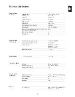
Страница 37: ...Netzimpedanz an der Schnittstelle PCC zum öffentlichen Netz keine EMV Emissionsklasse B Prüfzeichen CE Nominelle Ausgangsspannung 6 V 12 V 24 V DC Ausgangsspannungs Bereich 2 V 33 6 V Ausgangsstrom 35 A bei 28 8 V DC 35 A bei 14 4 V DC 35 A bei 7 2 V DC Batterie Rückstrom 1 mA 6 V 12 V 24 V DC 3 350 Ah Kühlung Konvektion und Lüfter Abmessungen l x b x h 270 x 168 x 100 mm Gewicht ohne Kabel 2 kg B...

Страница 38: ...36 IEC 60068 2 29 Wiederholte Stöße Repetitive shock 25 g 6 ms 1000 Stöße EN 60335 1 EN 60335 2 29 EN 61000 6 2 EN 61000 6 3 Class B EN 62233 EMF Norm ...

Страница 39: ... Principle 45 Device concept 45 Warning notices on the device 45 Start up 46 Safety 46 Proper use 46 Mains connection 46 Safety features standard protective equipment 46 Control elements and connections 48 General remarks 48 Control panel 48 Plugging in options 48 Connections 49 Removing covers for connections and options 50 Fitting the optional bracket and strain relief device for the charger lea...

Страница 40: ...ing refresh charging 62 Power supply mode 63 Requirements 63 Power Supply mode 63 Device options 65 General information 65 Selecting device options 65 Configuration 65 Synergic lines 67 Safety 67 Available characteristics 67 Troubleshooting 68 Safety 68 Protective equipment 68 Charging errors 69 Technical data 71 Electrical data input 71 Electrical data output 71 Battery data 71 Technical data 71 ...

Страница 41: ...tly or misused however it can cause injury or death to the operator or a third party damage to the device and other material assets belonging to the operat ing company inefficient operation of the device All persons involved in commissioning operating maintaining and servicing the device must be suitably qualified read and follow these operating instructions carefully The operating instructions mu...

Страница 42: ...r current input This may affect a number of types of device in terms of connection restrictions criteria with regard to maximum permissible mains impedance criteria with regard to minimum short circuit power requirement at the interface with the public mains network see Technical Data In this case the plant operator or the person using the device should check whether the device may be connected wh...

Страница 43: ...t circuits do not place any tools or conductive metals on the battery Battery acid must not get into the eyes onto the skin or clothes Wear pro tective goggles and suitable protective clothing Rinse any acid splashes thoroughly with clean water and seek medical advice if necessary Protect batteries from dirt and mechanical damage Store charged batteries in a cool place Self discharge is kept to a ...

Страница 44: ...e charger Never bypass or disable protection devices After the charger has been installed a freely accessible mains plug must be available Devices with emission class A are only designed for use in an industrial setting can cause grid bound and emitted interference in other areas Devices with emission class B satisfy the emissions criteria for residential and industrial areas This also applies to ...

Страница 45: ...rs from the date of invoice However the manufacturer will not accept any liability if the damage was caused by one or more of the following Use of the charger not in accordance with the intended purpose Improper installation and operation Operating the charger with faulty protection devices Non compliance with the operating instructions Unauthorised modifications to the charger Catastrophes caused...

Страница 46: ...be collected separately and returned to an ap proved recycling facility Any device that you no longer require must either be returned to your dealer or given to one of the approved collection and recycling facilities in your area Ignoring this European Directive may have potentially adverse affects on the environment and your health Copyright of these operating instructions remains with the manufa...

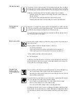
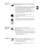
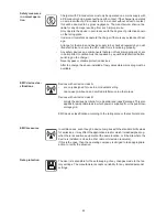
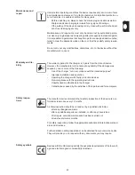
Страница 47: ...re requirements A wide range of options is available A 14 4 V voltage limit provides optimum protection for the vehicle electronics Warning notices on the device A number of safety symbols can be seen on the charger s rating plate The safety symbols must not be removed or painted over Do not use the functions until you have fully read all the operating instructions Possible sources of ignition suc...

Страница 48: ...ng safety features are provided as standard with the Active Inverter Voltage free and spark free terminals protect against explosions Reverse polarity protection prevents the charger from being damaged or destroyed Short circuit protection provides effective protection for the charger The fuse does not need to be replaced in the event of a short circuit A charging time monitor provides effective p...

Страница 49: ...47 g Overtemperature protection through derating charging current reduced if the temper ature rises above the permitted level ...

Страница 50: ...esult of firmware updates you may find that there are functions available on your unit that are not described in these operating instructions or vice versa Certain illustrations may also differ slightly from the actual control elements on your device However these controls function in exactly the same way WARNING Operating the equipment incorrectly can cause serious injury and damage Do not use th...

Страница 51: ...essage Immobiliser and common error message 4 Connection P1 charger lead socket used to connect the charger lead also for connecting the temperature controlled charging or external Start Stop op tions 5 Removable display 6 Connection P3 visual port for connecting the internal display 7 Connection P4 multiport for connecting the options Status lamp Software update via USB connection 1 2 3 4 6 7 5 ...

Страница 52: ...bracket and strain relief de vice for the charg er lead To fit the bracket Undo screws 1 Fit bracket 2 using the previously re moved screws To fit the strain relief device Undo screw 3 Fit charger lead strain relief device 4 using the previously undone screw Edge guard op tion The edge guard removal process is the re verse of the fitting process The bracket cannot be fitted if the edge guard is al...

Страница 53: ...e using spacer M8 DIN 125 or DIN 134 located as shown Installation The space requirement measurements in mm illustrated below are given to ensure that there is easy access to the plug connections 1 1 click click 120 mm 130 mm NOTE If the charger is installed in a switch cabinet or a similar separate area then forced air ventilation must be provided to ensure adequate heat dissipation There must be...

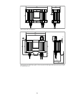
Страница 54: ...ements with edge guard Space requirements without edge guard and space requirements with signal lamp and bracket options space for installation removal 100 15 5 168 270 247 88 126 140 60 20 70 20 11 5 162 184 233 6 5 ...

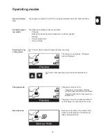
Страница 55: ...de Connect mains cable to charger and plug into mains The charger is on standby Charging mode is displayed Charging mode Charging mode is used for Charging or conservation charging with the battery either fitted or removed Charging while vehicle consumers are switched on Charging mode is automatically started af ter the charger is connected to the mains Back up mode Back up mode relieves the vehic...

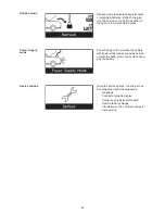
Страница 56: ...ply mode Power Supply mode provides the vehicle with power while repairs are being carried out with the battery removed or when chan ging the battery Device options Using the device options the charger can be configured in the following areas Language Contrast of graphic display Configure an individual standard Restore factory settings Information on the hardware and soft ware version ...

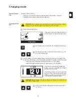
Страница 57: ...ger lead to the negative pole on the battery The charger automatically identifies the battery e g 12 V and starts the charging process after 5 seconds If the battery voltage is not correctly identi fied e g in the event of a deep discharge battery you have 5 seconds to enter the correct battery voltage as follows CAUTION Risk of damage when attempting to charge a faulty battery Before charging ens...

Страница 58: ...rd bar represents a state of charge of 80 All four bars are continuously display ed The state of charge is 100 The battery is ready to use The battery can remain connected to the charger for any length of time Conservation charging counteracts battery self discharge Disconnect the charger Disconnect the black charger lead from the negative pole on the battery Disconnect the red charger lead from t...

Страница 59: ...57 g Resuming charg ing Press the Stop Start key Charging is resumed 1 ...

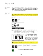
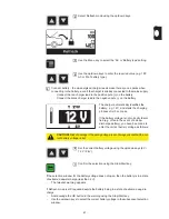
Страница 60: ...e positive pole on the battery Connect the black charger lead to the negative pole on the battery The charger automatically identifies the battery e g 12 V and starts the back up process after 5 seconds If the battery voltage is not correctly identi fied e g in the event of a deep discharge battery you have 5 seconds to enter the correct battery voltage as follows CAUTION Risk of damage when attem...

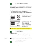
Страница 61: ...harger lead from the positive pole on the battery Interrupting Back up mode Resuming Back up mode CAUTION Risk of sparks if the charger leads are disconnected too soon Before disconnecting the charger leads press the Stop Start key to end Back up mode End Back up mode Press the Stop Start key 6 7 NOTE Risk of damage to connection sockets and plugs Do not disconnect or unplug the charging cable in ...

Страница 62: ... C Refresh mode can cause the battery temperature to rise to up to 45 C Immediately dis connect the charger if the battery temperature exceeds 45 C CAUTION Refresh charging may damage the vehicle electronics Disconnect and remove the battery from the vehicle before carrying out a refresh charge NOTE Use Refresh mode with caution as it can cause fluid loss or drying out Also ensure that the battery...

Страница 63: ...the battery voltage does not open then the battery is in a state of extreme deep discharge less than 2 V The relevant warning appears If Refresh mode is still required despite the battery being in a state of extreme deep dis charge Acknowledge the OK button in the warning using the Stop Start key Use the up down keys to select the correct battery voltage in the subsequent selection window Select R...

Страница 64: ...harger lead from the negative pole on the battery Disconnect the red charger lead from the positive pole on the battery Interrupting re fresh charging Resumingrefresh charging CAUTION Risk of sparks if the charger leads are disconnected too soon Before disconnecting the charger leads press the Stop Start key to finish charging To terminate Refresh charging Press the Stop Start key 8 9 NOTE Danger ...

Страница 65: ...d charger lead to the positive vehicle battery lead Connect the black charger lead to the negative vehicle battery lead A safety message appears on the display asking whether the charger leads are con nected correctly CAUTION An incorrect vehicle specific voltage setting can cause severe dam age to the vehicle electronics Before connecting the charger to the vehicle bat tery leads ensure that the ...

Страница 66: ...t the charger Disconnect the black charger lead from the negative vehicle battery lead Disconnect the red charger lead from the positive vehicle battery lead To cancel Power Supply mode Press the Stop Start key 7 8 ...

Страница 67: ...create an individual standard Charger lead length 1 m 10 m adjustable in 0 5 m stages The following lengths may be requested in the scope of supply 2 5 m 5 m and 10 m Initial values Start mode Charging Back up mode Battery capacity 3 350 Ah Battery type WET GEL and AGM Voltage selection automatic Use the up down keys to select the device options 1 CAUTION Risk of damage when selecting and using in...

Страница 68: ...66 optionally set permanently to 6 V 12 V or 24 V ...

Страница 69: ... instructions The battery must not be connected to the charger when setting parameters Operating mode Battery Characteris tic I1 U1 6 12 24V I2 U2 6 12 24V Charging WET IUoU 35 7 2 14 4 28 8 6 75 13 5 27 AGM GEL Back up mode All IU 35 6 75 13 5 27 Refresh WET IUIoU 35 7 2 14 4 28 8 4 6 75 13 5 27 AGM 1 2 GEL 7 05 14 1 28 2 Power Supply mode None IU 35 6 75 13 5 27 I1 Main charging current A maximu...

Страница 70: ...oltage WARNING An electric shock can be fatal Before opening the device Unplug the device from the mains Disconnect battery connection Put up an easy to understand warning sign to stop anybody inadvertently switching it back on again Using a suitable measuring instrument check to make sure that electrically charged parts e g capacitors have been discharged CAUTION Failure to connect a correctly di...

Страница 71: ...mperature sensor has tripped due to undertemperature Remedy Charge the battery in a more suitable area No 33 Optional external temperature sensor has tripped due to overtemperature Remedy Allow battery to cool or charge battery in a more suitable area No 34 Battery voltage set too high Remedy Set the correct battery voltage No 37 Conservation charge current too high Remedy Check for parallel consu...

Страница 72: ...dy Replace external temperature sensor Contact After Sales Service in the event of the following charger faults no 60 and above No 60 Device fault invalid characteristic number No 61 Device fault invalid characteristic block No 62 Device fault incorrect calibration values checksum No 63 Device fault incorrect device type ...

Страница 73: ...itted mains impedance at the inter face PCC to the public grid None EMC emission class B Marks of conformity CE Nominal output voltage 6 V 12 V 24 V DC Output voltage range 2 V 33 6 V Output current 35 A at 28 8 V DC 35 A at 14 4 V DC 35 A at 7 2 V DC Battery return current 1 mA 6 V 12 V 24 V DC 3 350 Ah Cooling Convection and fan Dimensions l x w x h 270 x 168 x 100 mm Weight without cable 2 kg O...

Страница 74: ...72 IEC 60068 2 29 Repetitive shock 25 g 6 ms 1000 shocks EN 60335 1 EN 60335 2 29 EN 61000 6 2 EN 61000 6 3 Class B EN 62233 EMF Standard ...

Страница 75: ...73 g ...

Страница 76: ......

Отзывы: