AKAI DIGITAL DR16 pro Скачать руководство пользователя страница 12

Version 3.11 Addendum

Page 10

MULTI-MACHINE OPERATION

Parameter Settings

For correct multi-machine synchronisation it is important that certain other parameters on
each DR16pro are set correctly. These should be configured automatically when the machines
are designated as a MASTER or SLAVE (as described in the previous step), but you may
like to confirm that these settings are correct following changes in the system setup that
may affect these parameters.

(i) Sample Rate

The sample rates of each DR16pro used in multi-machine system must be the same to
allow correct synchronisation. Changes in the sample rate on the MASTER machine will
automatically be transmitted to SLAVE machines as well

To confirm the sample rate setting:

1) Press the SUB-MENU key.

2) Press the 2 (DIGI) key.

3) Use the JOG/SHUTTLE control to select the 

SMPL RATE

SMPL RATE

SMPL RATE

SMPL RATE

SMPL RATE

 menu.

4) Press the STORE/ENT key.

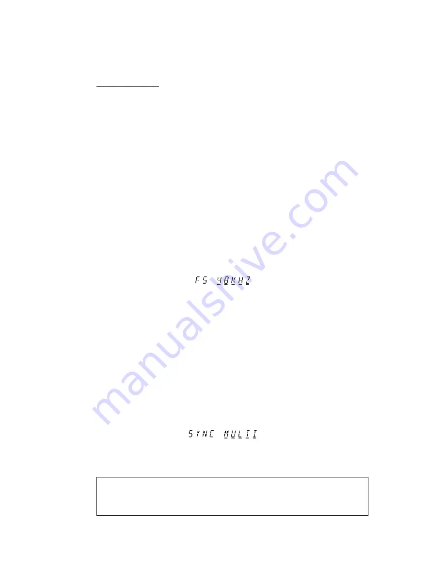
The current sample rate setting will be shown by a display such as this:

(ii) Sample Clock Source

When operating with multi-machine synchronisation, the SYNC IN/OUT connection on the
DR16pro is used to transmit a special signal from the MASTER machine which is used as a
sample clock source on the SLAVE machines. The selection of this source on the slave
machines is made automatically when the multi-machine synchronisation system is enabled.

To confirm the sample clock source setting on SLAVE machines:

1) Press the SUB-MENU key.

2) Press the 2 (DIGI) key.

3) Use the JOG/SHUTTLE control to select the 

DIGI SYNC

DIGI SYNC

DIGI SYNC

DIGI SYNC

DIGI SYNC

 menu.

4) Press the STORE/ENT key.

The sample source should be set to MULTI on each SLAVE machine:

On the MASTER machine, the clock source will usually be set to internal (XTAL), but may
also be set to clock the system from a digital audio source (DIGI or DINLR) when operating
the system using digital audio interfaces as described in the next section.

NOTE: Due to the use of the SYNC IN/OUT connector  to pass a special synchronisation
clock signal from the MASTER machine to other SLAVE machines, it is not currently
possible to use the system with Video Sync or Wordclock whilst using the multi-machine
synchronisation feature.

Содержание DR16 pro

Страница 1: ...HARD DISK RECORDER Operator s Manual WARNING To prevent fire or shock hazard do not expose this appliance to rain or moisture 000306 Printed in Japan Version 3 11 Addendum...

Страница 2: ...particular purpose In no event will AKAI professional M I Corp be liable for direct or indirect damages arising from any defect in the software or its documentation Further AKAI professional M I Corp...

Страница 3: ...3 Akainet Ethernet Connections 3 Sync Connections 4 MULTI MACHINE SETUP 7 Set Machine IDs 7 Master Slave Selection 8 Save Settings To Flash 9 MULTI MACHINE OPERATION 10 Parameter settings 10 Using Di...

Страница 4: ...function allows multiple DR16pro machines to be accurately synchronised for playback and recording The system uses a combination of the AKAINET connections on each machine to pass synchronisation mes...

Страница 5: ...used Akainet Ethernet Connections The AKAINET connectors on each DR16pro should be connected together to allow multi machine synchronisation messages to be passed from one machine to another This sho...

Страница 6: ...imum of 185m of cable in the system between the first and last nodes There should be at least 0 5m of cable between each connection Sync Connections The SYNC IN OUT connectors on each DR16pro should b...

Страница 7: ...nised multi machine system comprising 4 machines would therefore be connected as follows The AKAINET chain provides the necessary transport control etc whilst the SYNC IN OUT connection maintains accu...

Страница 8: ...in the chain it should have termination switched on Of course you may have more or less machines in your system however many you have remember that termination must be switched ON on the first and la...

Страница 9: ...play will show SUB MENU 2 Press the 3 SETUP key on the numeric keypad 3 Use the JOG SHUTTLE control to select the AKAINET menu You will see a display similar to the following 4 Press the STORE ENT key...

Страница 10: ...select the AKAINET menu You will see a display similar to the following 4 Press the STORE ENT key A message such as MACHINE 01 will appear on the display showing the currently selected Machine ID numb...

Страница 11: ...settings on each machine The following procedure should be repeated on each DR16pro in the system 1 Press the SUB MENU key 2 Press the 3 SETUP key 3 Use the JOG SHUTTLE control to select the FLASH SA...

Страница 12: ...e Clock Source When operating with multi machine synchronisation the SYNC IN OUT connection on the DR16pro is used to transmit a special signal from the MASTER machine which is used as a sample clock...

Страница 13: ...a multi machine setup however the following configuration would be appropriate Here the MASTER DR16pro Machine ID1 is used as the clock master and all other devices in the system are slaved to it Mach...

Страница 14: ...The following is likely to be the most appropriate configuration if you are using an external digital mixer In this setup the master DR16Pro ID1 receives sample clock from the mixer s digital outputs...

Страница 15: ...m Check the MACHINE IDs to ensure that each DR16pro has been assigned a unique ID number from 1 to the number of machines in the system This message indicates there has been a problem synchronising th...

Страница 16: ...ess the 3 SETUP key on the numeric keypad 3 Use the JOG SHUTTLE control to select the O S LOAD function You will see a display similar to the following 4 Press the STORE ENT key The message SCSI ID 0...

Страница 17: ...y from 0 to 100 as the new operating system is being programmed WARNING Do not switch off the DR16pro while the Flash ROM is being erased or programmed If you do the DR16pro may not reboot when next p...

Страница 18: ...the TASCAM meter unit supplied with the IB D8TIF can not be installed in the DR16pro Selecting TDIF Audio Inputs 1 Press the DIGI key The DIGI key will light to show that the inputs from the IB D8TIF...

Страница 19: ...wing 3 Use the JOG wheel to select TDIF NORM 4 Use the SHUTTLE control to move the cursor to the right hand field Turn the JOG wheel to select SWAP This will assign tracks 9 16 to the 8 outputs from t...

Отзывы: