– 7 –
1.
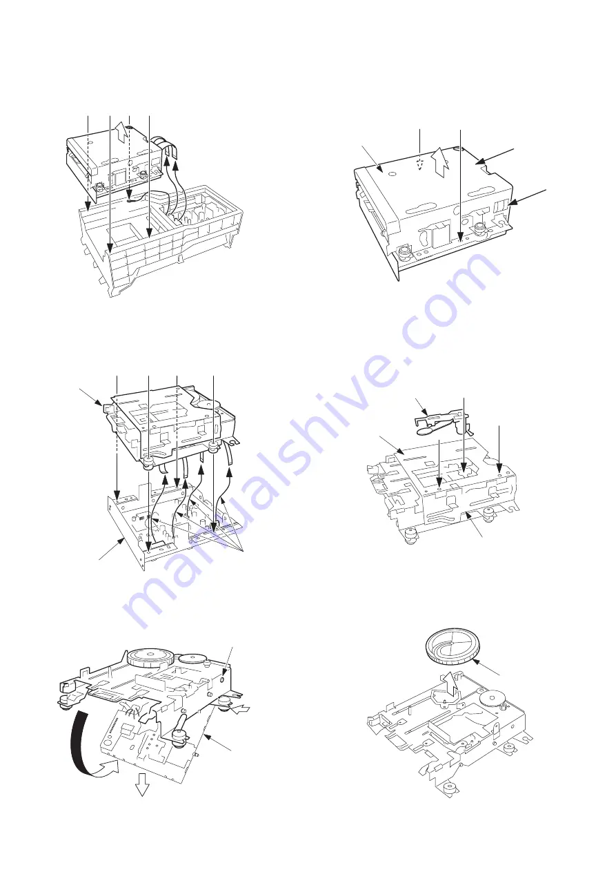
Remove the four screws (BVT2+3-10 W/O SLOT) of
A
.
Remove AZG-4 in the direction of the arrow.
DISASSEMBLY INSTRUCTIONS
A
A
A
A
2.
Remove the four screws (VTT+3-4) of
B
.
Set the mechanism in the PLAY state.
Remove the HLDR, SHIELD TOP in the direction of the
arrow.
HLDR, SHIELD TOP
B
B
B
B
C
C
D
D
MD MECHANISM
HLDR, SHIELD BOT
FFC
A
B
B
HEAD, OWH
PLATE, SLIDE R
PLATE ASSY,
SLIDE L
BOSS
ZZG-D
(b)
(a)
(c)
CAM, LOAD
3.
Remove the two screws (S-SCREW, MD TF) of
C
.
Remove the two screws (S-SCREW MD T) of
D
.
Remove the four FFCs and remove the MD
MECHANISM.
4.
Remove the screw (VW+1.7-5) of
A
.
Remove the HEAD, OWH.
Remove the two screws (VTT+2-3) of
B
.
Remove the PLATE ASSY, SLIDE L and the PLATE, SLIDE
R. in the direction of the arrow.
5.
Move the ZZG-D in the direction of arrow (a). While
pushing the BOSS in the direction of arrow (b), remove
it in the direction of arrow (c).
6.
Remove the CAM, LOAD in the direction of the arrow.
Disassembly Procedure
Содержание XR-HG5MD
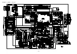
Страница 14: ...SCHEMATIC DIAGRAM 1 MAIN 1 2 AMP SECTION 14 ...
Страница 15: ...SCHEMATIC DIAGRAM 2 MAIN 2 2 TUNER SECTION 15 ...
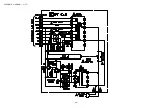
Страница 18: ...SCHEMATIC DIAGRAM 3 FRONT 18 ...
Страница 20: ...SCHEMATIC DIAGRAM 4 PT 20 ...
Страница 24: ... 24 IC BLOCK DIAGRAM IC LC72131D IC M61500FP ...
Страница 25: ... 25 IC BU2092F IC BA3835F ...
Страница 26: ... 26 IC LA1837NL IC BU2099FV ...
Страница 27: ... 27 IC BU1920FS ...
Страница 28: ... 28 FL HNA 13MM14T GRID ASSIGNMENT ANODE CONNECTION GRIDASSIGNMENT ...
Страница 29: ... 29 ANODECONNECTION ...
Страница 40: ...2 11 IKENOHATA 1 CHOME TAITO KU TOKYO 110 JAPAN TEL 03 3827 3111 Printed in Singapore 9420208 0251431 ...


