


– 16 –
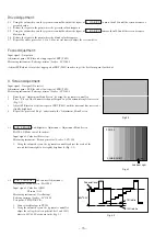
3-3. SUB TINT Sub-tint Adjustment / Adjustment Menu Screen : PAGE 3-3
Input signal : Color bar
VIDEO IN
Measuring instrument : Oscilloscope
Pattern generator/Leader : LCG-404
Test point : TP302/BT301 (wire connector) PIN 3
1. Connect oscilloscope to TP302.
2. Use the volume keys on the jig remote controller to adjust the lower
envelope of waveform tangential to the linear ramp as shown in Fig. 3-3.
3-4. SUB COLOR Sub-color Adjustment / Adjustment Menu
Screen : PAGE3-4
Input signal : Color bar
VIDEO IN
Measuring instrument : Oscilloscope
Pattern generator/Leader : LCG-404
Test point : TP302/BT301(wire connector) PIN 3
1. Connect oscilloscope to TP302.
2. Use the volume keys of the jig remote controller and adjust
the top and bottom excursions of waveform to be linear as
shown in the Fig. 3-4.
4.
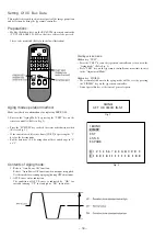
TV SETTING CHECK Checking of Setting per Model Basis / Adjustment
Menu Screen : PAGE 4-1 ~ 4
The setting details are fixed per model basis. Do not set other than specified.
•
Check whether the adjustment menu screen is matching to the table–4. If
not, use the volume keys on the jig remote controller to search and set the
matching menu screen to the model.
3.58 TRAP
0 : ON
BPF
2 : AUTO
H AFC
1 : +1
WPL
0 : OFF
* The contents for 3.58 TRAP can not be modified.
Table–4


