Aiwa TV-AN2110 Скачать руководство пользователя страница 14

– 14 –

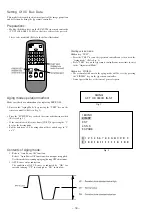
1-4.   OSD POS   OSD Positioning Adjustment / Adjustment Menu Screen :

PAGE 1-4

Input signal : Not specified

Using the volume keys on the jig remote controller, marks on both
side to be an equal distance from the edge of the screen. A=B  (Fig. 1-4)

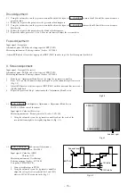
1-5.   PIF  VCO   VIDEO IF • VCO Adjustment / Adjustment Menu

Screen : PAGE 1-5

Input signal : ANT   RF - INPUT

                               Color bar

Measuring instrument : Pattern generator / Leader : LCG-404

Using the volume keys on the jig remote controller, adjust AFT
status on the screen to “OK”. (Fig. 1-5)

If there is more than one area to adjust, select the average
figure.

*

“NG” will be indicated for SD when no screen signal was sent.
It will not be any problem for VCO adjustment. (eg. Video
input environment with receiving no signal.)
Even in this case, adjustment is possible if there is a load on
ANT.

1-6.   RF  AGC   RF - AGC / Adjustment Menu Screen : PAGE 1-6

Input signal : ANT  RF - INPUT

                               Color bar

Test point : TP-101   RF - AGC   (TU101-PIN1)
Measuring instrument : Oscilloscope

                                 Pattern generator / Leader : LCG-404

1. Connect oscilloscope to TP101
2. Using the volume keys on the jig remote controller, adjust the test point

voltage becomes to 3.5

±

0.3V. And at the same time, confirm AFT status

changes to “OK” as shown in the Fig. 1-6.

2. White Balance Adjustment : 

Adjustment Menu Screen : PAGE 2-1 ~ 5

Input signal

: White raster

Contents of the adjustment : 1. R  CUT  OFF

2. G  CUT  OFF
3. B  CUT  OFF
4. G  DRIVE

* More than 20 minutes of aging

                                                                                     is required before adjusting.

5. B  DRIVE

* Whole adjustment process should

                                                                                     be repeated for several times.

Measuring instrument : Pattern generator / Leader : LCG-404

Cut Off Adjustment :

2-1. Input white raster signal by using pattern generator.
2-2. Fix the cut off figure for the brightest color on the screen at 127 and adjust the

other 2 cut off figures for a white picture by using the volume keys on the jig
remote controller.

* User’s picture quality will be cleared when

the adjustment menu screen appears.

PAGE 1

SD

AFT

6  RF  AGC

OK

OK

32

Fig.1-6

PAGE 1

OSD   POS

A

B

Fig.1-4

*

Содержание TV-AN2110

Страница 1: ...419 1S1 S U P P L E M E N T This Service Manual contains the additional information NOTICES BEFORE REPAIRING DISASSEMBLY INSTRUCTIONS and ADJUSTMENT for the model TV AN2110 NH If requiring the other i...

Страница 2: ...hock that is dangerous Take enough care to deal with it 6 Avoid an X ray Safety is secured against an X ray by giving considerations to the cathode ray tube and the high voltage peripheral circuit etc...

Страница 3: ...d bent the hook to remove the cap the spring characteristics of the hook could be lost and when reinstalled the cap would come off from the CRT anode button easily causing an accident Do not turn the...

Страница 4: ...e cap after installing it Never re use the hook when it has been deformed 1 If the anode cap is turned after it is installed it may come off Therefore arrange the high voltage cable before attaching t...

Страница 5: ...could turn and cause an installation defect 4 Turn over the rubber cap symmetrically on the left and right See Figure 3 4 Caution Take great care not to damage the anode cap Figure 3 3 5 Fit your fore...

Страница 6: ...ap turned over and visually check that the hook is engaged securely 9 Release your hand from the rubber cap of the anode cap Caution Cover the anode cap so that it does not lift 10 Hold the skirt of t...

Страница 7: ...ion of arrow 1 See Figure 4 1 5 MAIN C B REMOVAL 1 Remove connector CN401 2 Remove connector CN801 3 Remove connector CN802 4 Pull out the MAIN C B in the direction of the arrow 2 See Figure 4 1 Figur...

Страница 8: ...gnal has an amplitude of about 0 3 V with flat envelope Confirm that ratio of the burst signal amplitude and the red signal amplitude is 0 30 0 66 If the output signal does not conform with the specif...

Страница 9: ...wise looking from the CRT s back screen and disengage Be careful not to loose the lock ring too much If the magnet assembly has become shifted during adjustments secure it to the position in Fig 1 4 3...

Страница 10: ...of red and blue 7 While looking at the screen adjust the tilt of the deflecting yoke and tighten the DY lock screw 8 Shift the magnet assembly to the front toward the CRTfunnel stop movement before t...

Страница 11: ...undings 2 Insert wedges in three locations in the gap between the deflecting yoke and the surface of the CRT funnel in order to secure the deflecting yoke Refer to Fig 1 9 Position of wedge Fig 1 9 In...

Страница 12: ...R902 S901 R903 TP902 Electrical Adjustment BT301 C332 TP201 AFT IC301 J403 J401 IC403 IC405 L201 SIF TP302 TP203 FM DET TP101 RF AGC IC3 IC1 TU101 J402 FORCUS SCREEN T601 FBT SFR T601 FBT 3 IC407 C213...

Страница 13: ...generator Leader LCG 404 Using the volume keys on the jig remote controller adjust the dot mark in the centre of crosshatch screen to the exact vertical centre position by allocating an equal number...

Страница 14: ...bar Test point TP 101 RF AGC TU101 PIN1 Measuring instrument Oscilloscope Pattern generator Leader LCG 404 1 Connect oscilloscope to TP101 2 Using the volume keys on the jig remote controller adjust t...

Страница 15: ...4 1 Enter to the Adjustment Menu Screen by using the jig remote controller 2 Press 0 key of the 10 numeric channel keypad to get a horizontal single line screen Fig 2 2 3 Adjust SFR located at the low...

Страница 16: ...illoscope Pattern generator Leader LCG 404 Test point TP302 BT301 wire connector PIN 3 1 Connect oscilloscope to TP302 2 Use the volume keys of the jig remote controller and adjust the top and bottom...

Страница 17: ...Broadcast CH fc 45 75MHz Mode TUNER Test point INPUT TP 102 IF TU101 PIN 11 OUTPUT TP 201 AFT IC301 PIN 44 Adjustment point L205 P IF Measuring instrument Oscilloscope Pattern generator Leader LCG 40...

Страница 18: ...of general repairs Setting Of IIC Bus Data Aging mode operation method Make sure that do confirmation after replacing EEP ROM 1 Enter to the Aging Mode by pressing the TEST key on the remote controlle...

Страница 19: ...R CONTRAST PUSH CH UP DN KEY PUSH CH UP DN KEY PUSH CH UP DN KEY PUSH CH UP DN KEY PUSH CH UP DN KEY PUSH CH UP DN KEY PUSH CH UP DN KEY PUSH CH UP DN KEY PUSH 1 6 KEY PUSH 1 5 KEY PUSH 1 4 KEY PUSH 1...

Страница 20: ...2 11 IKENOHATA 1 CHOME TAITO KU TOKYO 110 JAPAN TEL 03 3827 3111 Printed in Singapore 9301978...

Отзывы: