– 36 –
CD TEST MODE
1. How to Activate CD Test Mode
While pressing and holding the function button, insert the AC plug.
When the test mode starts, the message, “ TEST” appears on the display.
2. How to Cancel CD Test Mode
Press the POWER button or remove the AC plug.
* The test mode is cancelled by other function keys during play.
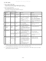
3. Function and Usage of CD Test Mode
No
Mode
Button for
Display
Operation
Contents
Activation
1
Start Mode
All lights are
All FL are lit.
• FL check
lit.
• Microcomputer check
2
Search Mode
STOP button
Reading
• Laser diode is lit during the
• APC circuit check
mode.
• Laser current measurement
• Focus search continuous
• Focus-search waveform check
operation. *1
• Focus-error waveform check
• Spindle motor continuous kick.
(DRF is ignored during search
mode)
3
Play Mode
PLAY button
Normal
• Normal playback.
• All servo circuits check
• Focus search continues if
• DRF check
TOC READ cannot be read.
4
Traverse
PAUSE
Normal
• Tracking Servo OFF/ON.
• Tracking balance check
Mode
button
The OFF/ON operation repeats
each time the PAUSE button is
pressed.
5
Sled Mode
FF button
TEST
• PU moves to inner track. *2
At the same time, the lens is
• Sled circuit check
kicked to inner track.
• Tracking circuit check
RWD button
TEST
• PU is moves to outer track. *2
• Mechanism operation check
At the same time, the lens is
• PU check
kicked to outer track.
6
Spindle Mode
REC/REC
All lights are
• When the button is pressed,
• Spindle circuit check
MUTE button lit.
the spindle motor operates in
• Spindle motor check
forward rotation (rough speed).
Then, the button is pressed
again, it operates in reverse
rotation.
When the button is pressed
again, operation stops.
*1 … When focus search operates continuously more than 10 minutes, the protection circuit may start due to generation of heat in the
driver IC. If this happens, turn off the power, leave the unit for a while, and then, restart.
*2 … Carefully monitor the gear against damage, as the sled motor rotates while the FF or RWD button is pressed even when the
pickup is located at innermost or outermost.
All manuals and user guides at all-guides.com
all-guides.com
Содержание NSX-T929
Страница 15: ...15 SCHEMATIC DIAGRAM 1 MAIN 1 6 FUNCTION SECTION All manuals and user guides at all guides com...
Страница 17: ...17 SCHEMATIC DIAGRAM 3 MAIN 3 6 AMP SECTION All manuals and user guides at all guides com...
Страница 18: ...18 SCHEMATIC DIAGRAM 4 MAIN 4 6 DECK SECTION HEAD 1 HEAD 2 All manuals and user guides at all guides com...
Страница 19: ...19 SCHEMATIC DIAGRAM 5 MAIN 5 6 DSP SECTION All manuals and user guides at all guides com...
Страница 20: ...20 SCHEMATIC DIAGRAM 6 MAIN 6 6 TUNER SECTION All manuals and user guides at all guides com...
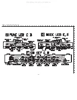
Страница 23: ...23 SCHEMATIC DIAGRAM 7 FRONT CD KEY DECK LED FUNC LED DECK All manuals and user guides at all guides com...
Страница 25: ...25 SCHEMATIC DIAGRAM 8 AMP 1F VM All manuals and user guides at all guides com...
Страница 27: ...27 SCHEMATIC DIAGRAM 9 PT All manuals and user guides at all guides com...
Страница 29: ...29 IC BLOCK DIAGRAM All manuals and user guides at all guides com...
Страница 30: ...30 All manuals and user guides at all guides com...
Страница 31: ...31 All manuals and user guides at all guides com a l l g u i d e s c o m...
Страница 37: ...37 MECHANICAL EXPLODED VIEW 1 1 All manuals and user guides at all guides com...

