– 33 –
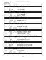
Pin No.
Pin Name
I/O
Description
63
NO-RHYTHM / P21
I/O
No rhythm (beat master) function rhythm input (Not used) / FL P21 segment output.
64
AC3-DPL / P20
I/O
AC 3 input + DOLBY PRO LOGIC detect input (Not used) / FL P20 segment output.
65
K-CON / P19
I/O
K-CON diode detect input (Not used) / FL P19 segment output.
66
RDS / P18
I/O
RDS function diode detect input (Not used) / FL P18 segment output.
67
FM1 / P17
I/O
OIRT diode detect input (Not used) / FL P17 segment output.
68
SW / P16
I/O
SW band diode detect input (Not used) / FL P16 segment output.
69
LW / P15
I/O
LW band diode detect input (Not used) / FL P15 segment output.
70
AM-10K / P14
I/O
AM-10K diode detect input / FL P14 segment output.
71
AM-ST / P13
I/O
AM stereo diode detect input (Not used) / FL P13 segment output.
72
VDD4
-
Connected to power supply.
73
REA / P12
I/O
Deck 2 side A recordable switch input / FL P12 segment output.
74
CST1 / P11
I/O
Deck 1 cassette detect input / FL P11 segment output.
75
CAM1 / P10
I/O
Deck 1 CAM switch input / FL P10 segment output.
76
AUTO2 / P9
I/O
Deck 2 auto stop input / FL P9 segment output.
77
AUTO1 / P8
I/O
Deck 1 auto stop input / FL P8 segment output.
78
CAM2 / P7
I/O
Deck 2 CAM switch input / FL P7 segment output.
79
REB / P6
I/O
Deck 2 side B recordable switch input / FL P6 segment output.
80
CST2 / P5
I/O
Deck 2 cassette detect input / FL P5 segment output.
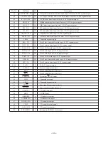
81~84
P4~P1
O
FL P4~P1 segment output.
85
K-SCAN
O
Key-scan output (active low).
86
SOL1
O
Deck 1 solenoid output (active low).
87
SOL2
O
Deck 2 solenoid output (active low).
88
O-MOTOR
O
Deck motor ON/OFF output.
89
VSS2
-
Connected to ground.
90
VDD2
-
Connected to power supply.
91
IFC-TU
I
Tuner tune-IF count input (active L).
92
I-STEREO
I
Tuner stereo detect input (active L).
93
I-SQDATA
I
CD SUBQ data input.
94
I-DRF
I
CD DRF input.
95
O-DISHREV
O
CD dish reverse output.
96
O-DISHFWD
O
CD dish forward output.
97
O-DATA (CD)
O
CD control data output.
98
CD-CE
O
CD control data latch output.
99
O-CLK (CD)
O
CD control clock output.
100
STB (SHIFT)
O
Shift register (BU2099) strobe output.
All manuals and user guides at all-guides.com
Содержание NSX-T929
Страница 15: ...15 SCHEMATIC DIAGRAM 1 MAIN 1 6 FUNCTION SECTION All manuals and user guides at all guides com...
Страница 17: ...17 SCHEMATIC DIAGRAM 3 MAIN 3 6 AMP SECTION All manuals and user guides at all guides com...
Страница 18: ...18 SCHEMATIC DIAGRAM 4 MAIN 4 6 DECK SECTION HEAD 1 HEAD 2 All manuals and user guides at all guides com...
Страница 19: ...19 SCHEMATIC DIAGRAM 5 MAIN 5 6 DSP SECTION All manuals and user guides at all guides com...
Страница 20: ...20 SCHEMATIC DIAGRAM 6 MAIN 6 6 TUNER SECTION All manuals and user guides at all guides com...
Страница 23: ...23 SCHEMATIC DIAGRAM 7 FRONT CD KEY DECK LED FUNC LED DECK All manuals and user guides at all guides com...
Страница 25: ...25 SCHEMATIC DIAGRAM 8 AMP 1F VM All manuals and user guides at all guides com...
Страница 27: ...27 SCHEMATIC DIAGRAM 9 PT All manuals and user guides at all guides com...
Страница 29: ...29 IC BLOCK DIAGRAM All manuals and user guides at all guides com...
Страница 30: ...30 All manuals and user guides at all guides com...
Страница 31: ...31 All manuals and user guides at all guides com a l l g u i d e s c o m...
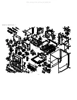
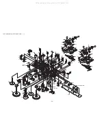
Страница 37: ...37 MECHANICAL EXPLODED VIEW 1 1 All manuals and user guides at all guides com...

