– 40 –
2. Service Mode 2
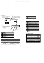
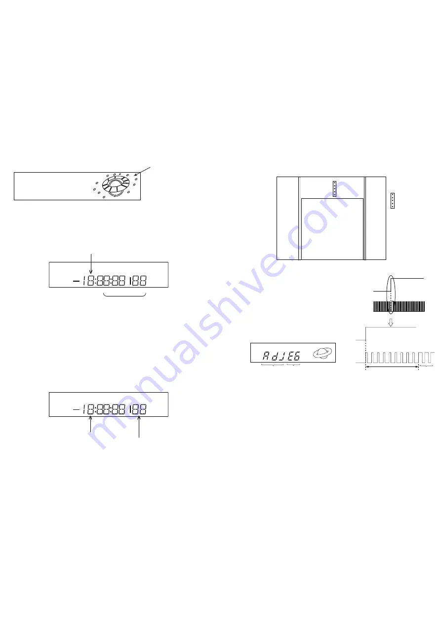
Display for the drum's revolution time (Displayed in decimal number)
SERVICE MODE NO. 2 BLINKS.
FL101
ACCUMULATED TIME (00000~16383 HOURS)
SERVICE MODE NO. 3 BLINKS.
DURING P-OFF, THE DATE IS DISPLAYED.
Light
FL101
To Reset accumulated time:
Accumulated time is reset by pressing CLEAR
key for more than 2 seconds or by replacing
E2PROM
* Do not reset in normal repairing.
3. Service Mode 3
The clock is advanced at 60 times the normal speed. When
this mode is used to check clock.
ELECTRICAL ADJUSTMENT
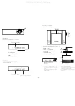
1. Switching Position Adjustment
MODE: PB
TTV-P1
Oscilloscope:
CH-1: CN301
3
HSW-V
CH-2: CN301
4
C-SYNC
Adjustment Method
1)
Set the tracking to the center.
*
Short TR-RST (CN301
5
) to GND. (CN301
2
)
An indication appears on the FL display tube indicating
that the machine is in the adjustment mode.
2)
Press “A-TR” key in the remote controller, to activate
HSW adjustment. FL diaplay will now indicate flashing
“AdJ”.
FL display indicates cassette tape controller after HSW
adjustment is finished.
3)
Check “t” value with the oscilloscope.
Change the adjustment value using the CH(+),(-) keys of
main unit until “t”specification is satisfied.
4)
To cancel the adjustment mode, press STOP key or turn
OFF the power.
Expanded
CH1
(V RF SWP)
CH2
(C SYNC)
t : 6.5H
±
0.5H
(416
±
32
µ
sec)
V. sync
Adjustment value
Adjustment mode
indicates "AdJ"
CN301
TOP VIEW
CN301
5. TR-RST
4. C-SYNC
3. HSW-V
2. GND
1. PB RF
TUNER
C.B
PS
C.B
1
5
1
5
Mechanism
NOTE : Adjust switching position after reassembling mechanism assy.
All manuals and user guides at all-guides.com
Содержание HV-FX8700
Страница 3: ...3 All manuals and user guides at all guides com...
Страница 12: ...12 C WIRE HARNESS DIAGRAM All manuals and user guides at all guides com...
Страница 13: ...BLOCK DIAGRAM 1 SYSCON SERVO 13 All manuals and user guides at all guides com...
Страница 14: ...BLOCK DIAGRAM 2 VIDEO 14 All manuals and user guides at all guides com...
Страница 15: ...BLOCK DIAGRAM 3 HIFI THEATRE 15 NOT USE WIDE WIDE All manuals and user guides at all guides com...
Страница 16: ...16 BLOCK DIAGRAM 4 TUNER All manuals and user guides at all guides com a l l g u i d e s c o m...
Страница 17: ...17 BLOCK DIAGRAM 5 MPX All manuals and user guides at all guides com...
Страница 18: ...BLOCK DIAGRAM 6 CANAL 18 SWITCH Q610 WIDE All manuals and user guides at all guides com...
Страница 19: ...19 BLOCK DIAGRAM 7 POWER PS All manuals and user guides at all guides com...
Страница 22: ...22 SCHEMATIC DIAGRAM 2 MAIN 2 4 VIDEO SECTION All manuals and user guides at all guides com...
Страница 23: ...23 SCHEMATIC DIAGRAM 3 MAIN 3 4 HIFI SECTION All manuals and user guides at all guides com...
Страница 25: ...25 SCHEMATIC DIAGRAM 4 FR1 FR2 All manuals and user guides at all guides com...
Страница 27: ...27 SCHEMATIC DIAGRAM 6 REAR 2 2 CANAL SECTION All manuals and user guides at all guides com...
Страница 29: ...29 SCHEMATIC DIAGRAM 7 TUNER All manuals and user guides at all guides com...
Страница 30: ...30 SCHEMATIC DIAGRAM 8 MAIN 4 4 POWER SECTION All manuals and user guides at all guides com...
Страница 31: ...31 SCHEMATIC DIAGRAM 9 PS All manuals and user guides at all guides com a l l g u i d e s c o m...
Страница 32: ...32 SCHEMATIC DIAGRAM 10 MPX All manuals and user guides at all guides com...
Страница 38: ...38 IC BLOCK DIAGRAM All manuals and user guides at all guides com...

