


– 4 –
DISASSEMBLY INSTRUCTION
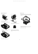
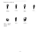
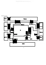
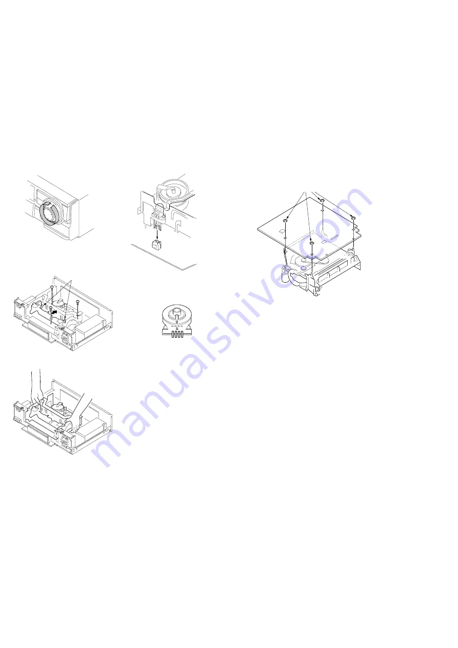
1. How to Remove the JOG/SHUTTLE
Wrap a tape around the JOG/SHUTTLE and remove it.
2. How to Remove the Mechanism
NOTE:Adjust switching position after reassembling mechanism assy.
Slide the cassette holder (as shown in the illustration), and remove the three
screws fixing the MAIN BASE of the mechanism deck.
Raise the mechanism deck and remove it.
Note:
Never hold the TOP BRACKET of the mechanism.
Lock lever
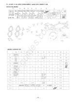
3. Caution When Attaching the Mechanism
Be careful when attaching the MAIN C.B. to mechanism that the leg
leads of the erase head must be correctly inserted.
Be careful when attaching the MAIN C.B. to mechanism that the
marked position of the rotary switch on the MAIN C.B. must agree
with the corresponding marking on the MAIN C.B. (See the above
illustration.)
MAIN C.B
Mechanism
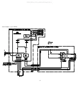
The washers that fix the MAIN C.B., are prepared to be used for service, for the purpose
that the mechanism can be easily set in the service position while the main power of the
machine is turned on. Attach the four washers to the four feet of the mechanism. (See the
illustration below.)
This model has the structure that the MAIN, TU and PS C.B. are removed together with
the rear panel when the rear panel is removed.
At the same time, be careful not to touch the power supply block during repair work.
Part No. 87-067-505-010 PW, 2.5-6-0.5 SLT
SERVICE POSITION
Front
Washers
MAIN C.B
Rear
Mechanism
All manuals and user guides at all-guides.com
Содержание HV-FX8700
Страница 3: ...3 All manuals and user guides at all guides com...
Страница 12: ...12 C WIRE HARNESS DIAGRAM All manuals and user guides at all guides com...
Страница 13: ...BLOCK DIAGRAM 1 SYSCON SERVO 13 All manuals and user guides at all guides com...
Страница 14: ...BLOCK DIAGRAM 2 VIDEO 14 All manuals and user guides at all guides com...
Страница 15: ...BLOCK DIAGRAM 3 HIFI THEATRE 15 NOT USE WIDE WIDE All manuals and user guides at all guides com...
Страница 16: ...16 BLOCK DIAGRAM 4 TUNER All manuals and user guides at all guides com a l l g u i d e s c o m...
Страница 17: ...17 BLOCK DIAGRAM 5 MPX All manuals and user guides at all guides com...
Страница 18: ...BLOCK DIAGRAM 6 CANAL 18 SWITCH Q610 WIDE All manuals and user guides at all guides com...
Страница 19: ...19 BLOCK DIAGRAM 7 POWER PS All manuals and user guides at all guides com...
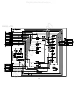
Страница 22: ...22 SCHEMATIC DIAGRAM 2 MAIN 2 4 VIDEO SECTION All manuals and user guides at all guides com...
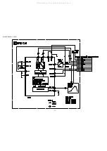
Страница 23: ...23 SCHEMATIC DIAGRAM 3 MAIN 3 4 HIFI SECTION All manuals and user guides at all guides com...
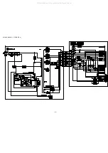
Страница 25: ...25 SCHEMATIC DIAGRAM 4 FR1 FR2 All manuals and user guides at all guides com...
Страница 27: ...27 SCHEMATIC DIAGRAM 6 REAR 2 2 CANAL SECTION All manuals and user guides at all guides com...
Страница 29: ...29 SCHEMATIC DIAGRAM 7 TUNER All manuals and user guides at all guides com...
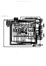
Страница 30: ...30 SCHEMATIC DIAGRAM 8 MAIN 4 4 POWER SECTION All manuals and user guides at all guides com...
Страница 31: ...31 SCHEMATIC DIAGRAM 9 PS All manuals and user guides at all guides com a l l g u i d e s c o m...
Страница 32: ...32 SCHEMATIC DIAGRAM 10 MPX All manuals and user guides at all guides com...
Страница 38: ...38 IC BLOCK DIAGRAM All manuals and user guides at all guides com...


