

EN
5
INSTALLATIONS
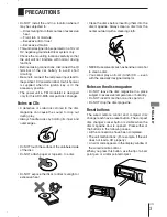
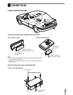
Precautions
Select the mounting location very carefully,
referring to the following points.
• Make sure that there is no fuel tank, wiring or
piping on the other side of the mounting surface.
• Make sure that the installation of the unit will not
hinder the movement of the deck lid or interfere
with the spare tire, etc.
• Use only the supplied mounting kit for safe and
proper installation.
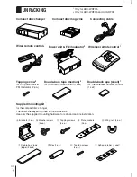
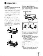
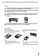
Removing the transport screws
Find the four transport screws at the bottom of the
unit, which lock the unit's mechanism during
transport. Remove these screws before
installation and attach the supplied adhesive
labels over the holes.
Retain these screws and replace them in the
original positions if the unit is transported for
service or maintenance.
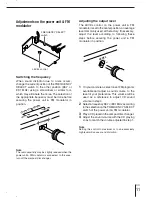
Mounting angle setting dials
Be sure to change the position of the mounting
angle setting dials according to the angle at
which the unit is to be installed.
For example, in relevance to the diagram above,
the following procedure would be used to change
the position from H (horizontal) to V (vertical).
1
Remove the locking screw.
2
Using the supplied key, turn the dial to the
position corresponding to the angle at which
the unit is to be installed.
H: Horizontal/suspended installation
45: 45° (slanted) installation
V: Vertical installation
3
Install the locking screw in the corresponding
hole.
4
Follow the same procedure for the other side
of the unit.
Note
• The mounting angle setting dials on each side of the
unit are factory-set to the H (horizontal) position.
1
3
2
H
V
45
H
V
45
H
V
45
Mounting angle setting dial
Содержание ADC-M35
Страница 16: ...87 KM1 901 01 970123ATM OX Printed in Korea A...


