Record the information found on the cable tag for future reference.
Part No.__________Date__________Frequency______________
17-626-01-rev.02
09/12/17
Owner’s Guide & Installation Instructions
Electromagnetic
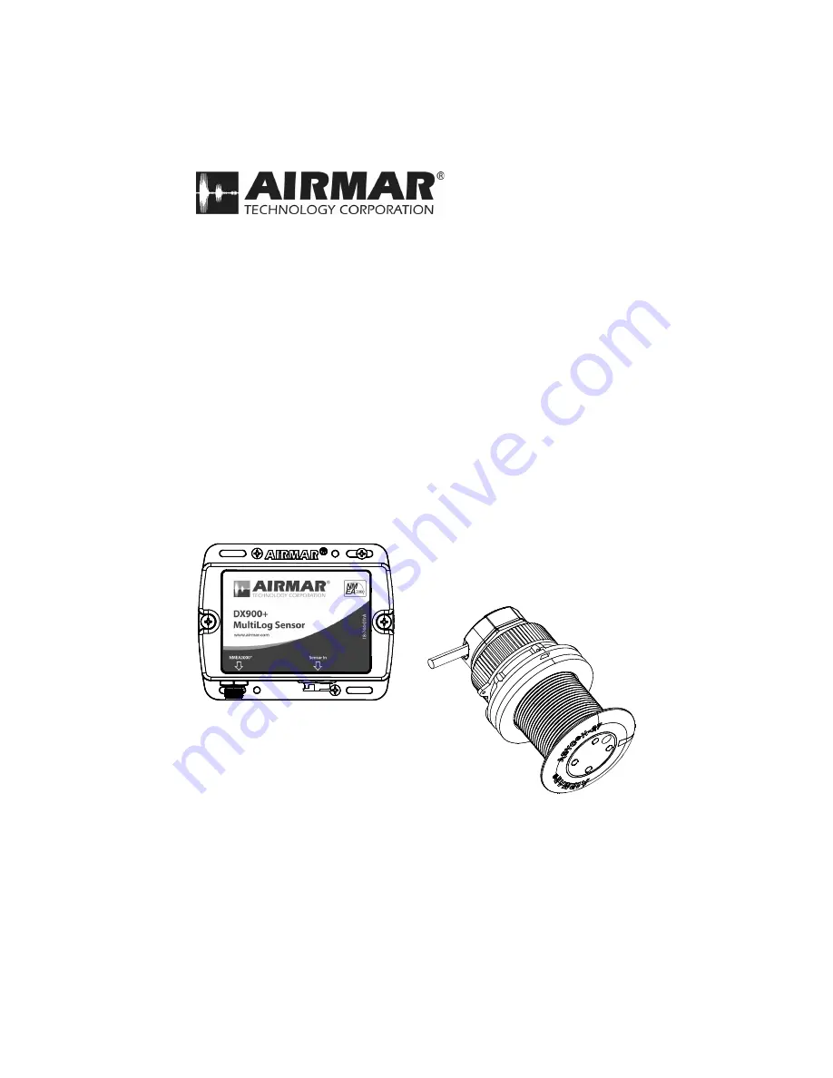
Multilog Sensor
Smart
™
Sensor
Model
DX900+


