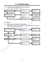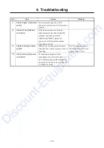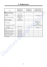
4. Troubleshooting
4-9
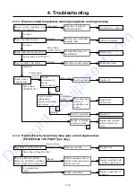
4.2.9
Purge control operation will not start even if auto idle switch is pressed
※
1
:
As the output voltage of intake negative pressure sensor at unload operation is very little, it is
better to check the function of purge control operation after replacing the sensor with new one,
if it is found difficult to diagnose the trouble.
Lower than
30
%
Faulty setting of
purge starting intake
negative pressure
(VR2) percentage.
Adjust (See 1.6.2)
30
%
10sec
No air leak found
Service air piping
leaking
Air leak found
Repair air piping.
Faulty setting of purge
transfer timer (VR1).
Setting timer
too long.
Adjust (See 1.6.2)
Check auto idle switch cable
connection.
Disconnection or
defective contact of
cable connection
between controller -
auto idle switch -
ground connection.
Cable
disconnected
Repair connection.
Trouble of intake
negative pressure
sensor
Abnormal output
voltage found
Replace it.
Not cable disconnected
Key ON when stopping
:
DC0.5V
At unload
:
less than DC0.5V
Trouble of
purge/starting
unloader solenoid
valve
At no load
:
electrically
connected
Repair or replace.
Check wiring connection
between controller and
purge/starting unloader
solenoid valve and fuses.
Repair connection.
Trouble of controller
Repair or replace.
At no load
:
electrically connected
Cable
disconnected
Not cable disconnected
Cable disconnection
between controller and
purge/starting
unloader solenoid
valve or defective
contact found
Disconnection and
faulty contact between
controller and intake
negative pressure
sensor
Cable
disconnected
Repair connection.
Not cable disconnected
※1
Check service piping for any
air leak.
Check setting of purge
starting intake negative
pressure (VE2).
Check setting of purge
transfer waiting timer
(VR1).
Check intake negative
pressure sensor output
voltage of “Key ON when
stopping” and “At
unload”(See 3.1.8)
Check cable connection
between intake negative
pressure sensor and
controller.
Check electrical connection
to purge/starting unloader
solenoid valve.
Discount-Equipment.com
Содержание PDS185S-6C1
Страница 1: ...D i s c o u n t E q u i p m e n t c o m...
Страница 9: ...1 Specification 1 5 A070356 Unit mm PDS185S 6C1 VE PUMP Type D i s c o u n t E q u i p m e n t c o m...
Страница 10: ...1 Specification 1 6 PDS185S 6C1R IN LINE PUMP Type A070195E Unit mm D i s c o u n t E q u i p m e n t c o m...
Страница 19: ...1 Specification 1 15 1 7 Piping Diagram PC08091E D i s c o u n t E q u i p m e n t c o m...
Страница 20: ...1 Specification 1 16 1 8 Fuel piping PDS185S 6C1 VE PUMP Type PC08018E D i s c o u n t E q u i p m e n t c o m...
Страница 21: ...1 Specification 1 17 PDS185S 6C1R IN LINE PUMP Type PC08019 1E D i s c o u n t E q u i p m e n t c o m...
Страница 37: ...3 Electric System 3 5 2 PDS185S 6C1R IN LINE PUMP Type PC08028E D i s c o u n t E q u i p m e n t c o m...
Страница 38: ...3 Electric System 3 6 2 Function timing upon starting PC08029E D i s c o u n t E q u i p m e n t c o m...
Страница 75: ...5 3 5 2 Engine Wiring Diagram PDS185S 6C1 VE PUMP Type PC08046E D i s c o u n t E q u i p m e n t c o m...
Страница 76: ...5 4 PDS185S 6C1 VE PUMP Type PC08047E D i s c o u n t E q u i p m e n t c o m...
Страница 77: ...5 5 PDS185S 6C1R IN LINE PUMP Type PC08048E D i s c o u n t E q u i p m e n t c o m...
Страница 78: ...5 6 PDS185S 6C1R IN LINE PUMP Type PC08090E D i s c o u n t E q u i p m e n t c o m...
Страница 79: ...D i s c o u n t E q u i p m e n t c o m...


