background image

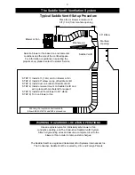
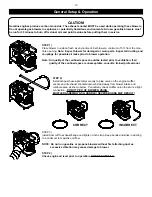
typical Saddle Vent® Setup Procedure

Place fan or blower a minimum of

5 ft. (1.6m) from manhole opening

Blower or Fan

90° Elbow

Manhole

Opening

Manhole Lid

Universal Mount

Saddle Vent®

Select a blower or fan based on environmental

conditions and the size of the confi ned space.

For information or guidance in selecting the

proper set-up, please contact Customer Service.

STEP 1)  Install 6 ft. (1.8m) duct on blower or fan

STEP 2)  Install 90° elbow on top of Saddle Vent®

STEP 3)  Install duct on bottom of Saddle Vent®

STEP 4)  Install universal mount on Saddle Vent® and

               set in place with manhole lid for support

STEP 5)  Install duct from blower to 90° elbow

STEP 6)  Turn on blower or fan

Warning: For explosive environments,

follow ANSI/API 2015 and 2016 procedures

The Saddle Vent® is a registered trademark of Air Systems International, Inc.

The Conductive Saddle Vent® is covered by U.S. and Foreign Patents

WArNiNG: HAZArDoUS loCAtioN oPErAtioNS

Use an explosion-proof or intrinsically safe blower or fan, 

conductive ducting, and The Conductive Saddle Vent® System.

Attach all grounding wires and assure a complete circuit to the

blower or fan in order to remove static charges.

the Saddle Vent® Ventilation System

3

Содержание SVB-A8

Страница 1: ...ll Free 1 800 866 8100 Fax No 757 424 5348 www airsystems com e mail sales airsystems com This manual must be read carefully and followed by all persons who have or will have the responsibility for using or servicing this equipment This equipment will perform as designed only if used according to the instructions Otherwise it could fail to perform as designed causing personal injury or death WARNI...

Страница 2: ...cal position or with the flange or guards removed Note If volatile or explosive vapors are suspected use Air Systems explosion proof electric blower Model No SVB E8EXP explosion proof in line fan Model No SVF 10EXP explosion proof contractors fan Model No CVF 8EXP or Air Systems intrinsically safe pneumatic blower Model No SVB A8 Note For confined space ventilation in non hazardous locations use A...

Страница 3: ...dle Vent STEP 4 Install universal mount on Saddle Vent and set in place with manhole lid for support STEP 5 Install duct from blower to 90 elbow STEP 6 Turn on blower or fan Warning For explosive environments follow ANSI API 2015 and 2016 procedures The Saddle Vent is a registered trademark of Air Systems International Inc The Conductive Saddle Vent is covered by U S and Foreign Patents WArNiNG HA...

Страница 4: ... 3 Connect to 120 VAC 60 Hz 15 amp service All standard electric blowers listed are supplied with a GFI Ground Fault Interrupter plug per the 1996 NEC code require ment Section 305 6 Note If an extension cord is required the minimum recommended size is 12 AWG maximum 100 ft For further information refer to the National Electric Code Tables Article 400 The use of generators is not recommended unles...

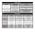
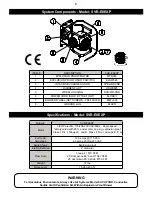
Страница 5: ...el SVB E8EC SVB E8 SVB E8 2 Motor 1 2 HP 37 kw electric 115 VAC 60 Hz single speed GFI cord installed 3 4 HP 56 kw electric 115 VAC 60 Hz single speed GFI cord installed 3 4 HP 56 kw electric 115 VAC 60 Hz two Speed GFI cord installed Full Load Amperage 8 0 amps 10 8 amps 11 2 amps Flow Rates Free air 1390 CFM 25 ft duct with one 90 bend 931 CFM 25 ft duct with two 90 bends 779 CFM Free air 1570 C...

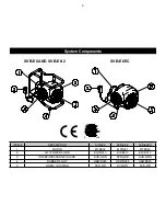
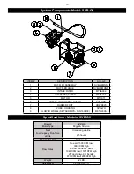
Страница 6: ...IPTION SVB E8 SVB E8 2 SVB E8EC 1 MOTOR MTR002 MTR021 MTR040 2 GFI POWER CORD ELCB013 ELCB013 ELCB013 3 INTAKE DISCHARGE GUARD SVB GRD SVB GRD SVB GRD 4 RUBBER FOOT HDWR025 HDWR025 HDWR025 5 WHEEL HOUSING SVB WH SVB WH SVB WH 6 System Components ...

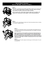
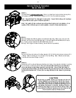
Страница 7: ...I Div I Groups E F G specifications The plug should not be disconnected or connected in an explosive environ ment when the blower is energized STEP 4 Switch the explosion proof ON OFF switch to the ON position The unit is now operational CAUTION If explosive or volatile vapors are suspected or present follow ANSI API procedure 2015 and 2016 for proper grounding of the blower All static electricity...

Страница 8: ...tory wired with 25 ft power cord no plug explosion proof Class I Div I Groups C and D Class II Div I Groups E F G Full Load Amperage 12 6 amps 115 VAC 6 3 amps 208 230 VAC Switch Type Explosion proof Inlet Outlet Size 8 diameter Flow Rate Free air 1570 CFM 25 duct w one 90 bend 1047 CFM 25 duct w two 90 bends 873 CFM Weight 72 lbs Noise Level 76 dbA 3 ft WARNING For Hazardous Environments Always U...

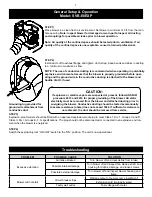
Страница 9: ...curely attached to the blower s grounding wire STEP 2 Attach and tighten the filter regulator and lubricator assembly Make sure oil level in the lubricator is at the full mark approximately 3 4 of bowl height add additional oil if neces sary Factory recommended oil is F44200 Parker tool oil viscosity 100 or higher mineral oil base Sunvis 932 or equivalant STEP 3 Secure a primary air source with a ...

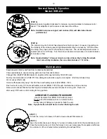
Страница 10: ...ted in regulator after approximately 300 500 hours Factory recommended oil is SAE 10 non detergent automotive engine oil or lighter Petroleum based only do not use synthetic oils Clean muffler assembly every 100 300 hours with safety solvent Part BAC 1001 Flush air motor every 100 hours with safety solvent BAC 1001 through maintenance port see below Remove air exhaust filter before flushing and re...

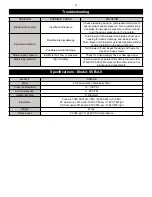
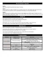
Страница 11: ... blower off and inspect housing and frame for cracks or loose screws Blower loses pressure Insufficient air flow or pressure Check for kinked supply hose or damaged duct Motor icing interior High humidity Install moisture separator filter before blower order Model PF 240 Remove muffler and clean out ice blockage and reassemble Model SVB A8 Motor 4 HP pneumatic intrinsically safe Pressure Required ...

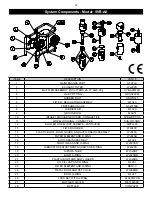
Страница 12: ...SCREWS FS5 16X038 METL039 13 FILTER HOLDER WL040C 14 PLASTIC BOWL BOWL GUARD AND AUTO DRAIN ASSEMBLY WL040A 15 FILTER ELEMENT AND O RING WL040B 16 AUTO DRAIN ASSEMBLY WL024 17 SIGHT GLASS AND O RING WL020SD 18 LUBRICATOR ADJUSTMENT SCREW AND O RING WL020A 19 SIPHON TUBE WL020BF 20 BOWL O RING WL020OR 21 PLASTIC BOWL AND BOWL GUARD WL020BA 22 OIL FILL CAP AND O RING WL057 23 FILTER ELEMENT AND O RI...

Страница 13: ... tested prior to ventilation If air quality of the confined space is unacceptable consult a trained professional STEP 2 Install exhaust hose assembly securely to pipe union on the engine muffler Locate end of exhaust snorkel down wind and away from blower intake and manhole area as shown below Periodically check muffler union to assure a tight connection DO NOT PICK UP BLOWER USING MUFFLER ASSEMBL...

Страница 14: ...amage Turn fan off and inspect housing and frame for cracks or loose screws Engine will not start No fuel Refuel Fouled or faulty spark plug Remove clean re gap or replace spark plug ON OFF switch in the OFF position Place switch in the ON position I ON O OFF Dry rotted fuel hose Replace fuel hose Allow exhaust snorkel pipe to cool before removing from engine Heat resistant gloves are recommended ...

Страница 15: ...OT HDWR025 8 WHEEL HOUSING SVB WH 9 BLOWER WHEEL SET SCREWS FS5 16X038 METL039A Model SVB G8 Motor Type Briggs Stratton Fuel Unleaded gasoline Fuel Capacity Run Time at Idle 2 5 hours Inlet Outlet Size 8 diameter Flow Rates Free air 1500 CFM low 3000 CFM high 25 duct w one 90 bend 1040 CFM low 1725 CFM high 25 duct w two 90 bends 870 CFM low 1295 CFM high Weight 62 LBS Noise Level 92 5 dbA 3 ft Sp...

Страница 16: ...SHAll tHE SEllEr BE liABlE For loSS oF ProFitS ANy otHEr DirECt or iNDirECt CoStS EXPENSES loSSES or DAMAGES AriSiNG oUt oF DEFECtS iN or FAilUrE oF tHE ProDUCt or ANy PArt tHErEoF The purchaser shall be solely responsible for compliance with all applicable Federal State and Local OSHA and or MSHA requirements Although Air Systems International believes that its products if operated and maintained...

Отзывы: