background image

2.

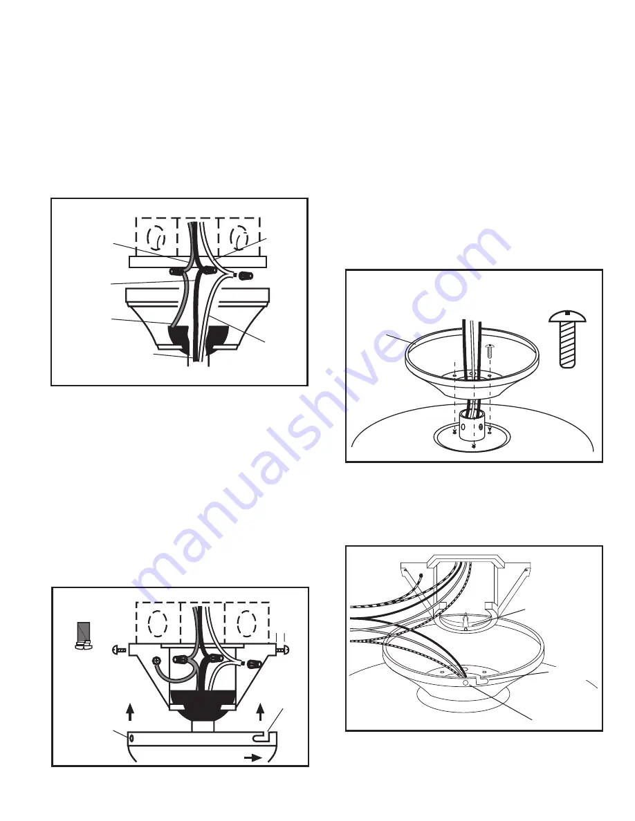
Raise the canopy up to the mounting bracket. Apply light pressure
upward on the canopy while rotating it to the right until the two
screws from step #1 drop into the side hook slots in the canopy.
Continue rotation until the canopy is fully locked and stops
rotating 

(Figure 5)

.

3.

Insert the last two screws through the remaining side holes of
the canopy into the mounting bracket. Tighten all four screws.

CAUTION:


MAKE SURE THAT THE ELECTRICAL WIRES ARE

COMPLETELY INSIDE THE ELECTRICAL BOX AND NOT PINCHED
BETWEEN THE CEILING CANOPY AND THE CEILING.

4.

Proceed to 

Section 9


Installing Fan Blades

SECTION 6

Close to Ceiling Mounting

1.

Set canopy flush against motor housing. Attach canopy with
three 3/16"-24x3/8" truss screws 

(Figure 6)

.

WARNING:


FAILURE TO COMPLETELY TIGHTEN THE TRUSS

SCREWS COULD RESULT IN THE FAN LOOSENING AND POSSIBLE
FAILING.

2.

Lift motor housing assembly and hang on mounting bracket post
through one of the two holes in the canopy 

(Figure 7)

.

CAUTION:


ONLY HANG FAN THROUGH CANOPY HOLE, DO

NOT HANG FAN THROUGH HOOK SLOT WHEN WIRING.

www.airkinglimited.com

980051015 Rev B. 9-05

3 of 8

CAUTION:


MAKE SURE POWER IS SWITCHED OFF AT

SERVICE PANEL BEFORE STARTING INSTALLATION.

NOTE:

 If a light fixture is being installed with the fan, follow the

fixture’s owner’s manual for wiring. This fan is adaptable to center-
mount light kits only.

1.

Make sure the electrical box is properly secured. Connect the
White wire from the fan to the White wire from the supply.
Connect the Black and Blue wires from the fan to the Black (hot)
wire from the supply. Connect the Green (ground) wire from the
fan to the Green or Bare Copper ground wire from the supply.
Use approved methods for all connections. Carefully push wires
up into the outlet box 

(Figure 4)

.

CAUTION:


CHECK TO CONFIRM THAT ALL CONNECTIONS

ARE TIGHT, INCLUDING THE GROUND, AND THAT NO BARE WIRE
IS VISIBLE AT THE CONNECTIONS, EXCEPT IN THE CASE THAT A
BARE WIRE WAS USED FOR THE GROUND WIRE.

SECTION 5

Installing the Canopy (Downrod)

1.

Use four #10-24x3/8" Phillips head screws with split lockwashers
to mount the canopy. Insert one screw in side hole of mounting
bracket, being careful not to fully tighten. Leave a minimum of
1/8" distance between the screw head and mounting bracket.
Locate the hole on the opposite side of the first screw and insert
the second screw, being careful not to fully tighten. Leave a
minimum of 1/8" distance between the screw head and mounting
bracket 

(Figure 5)

.

Figure 5

10-24 x 3/8" Phillips

head screw with

split lockwasher

Turn to right to lock

1/8"

Side hook

slot

Hole

Mounting
Bracket Post

Hole

Figure 7

Figure 4

Ground

Ground

Hot (Black)

White

Supply from home

from fan

White

Hot (Black and Blue)

Hook Slot

Canopy

3/16"-24x3/8"
Truss Screw

Figure 6

Содержание Builder's Choice 9800

Страница 1: ... must be done by qualified person s in accordance with all applicable codes and standards including fire related construction CAUTION THIS FAN MUST NOT BE USED IN POTENTIALLY DANGEROUS LOCATIONS SUCH AS FLAMMABLE EXPLOSIVE CHEMICAL LADEN OR WET ATMOSPHERES 5 Make certain that the power source conforms to the electrical requirements of the fan 6 The fan must be hung with at least 7 feet of clearanc...

Страница 2: ...arked Acceptable For Fan Support using the screws provided with the outlet box Insert the screws through the slotted holes in the bracket and attach to the electrical box Tighten both screws to the electrical box Figure 1 Figure 1 Screw Electrical Box Mounting Bracket CAUTION IF BRACKET AND OR ELECTRICAL BOX ARE NOT SECURELY ATTACHED THE FAN COULD WOBBLE SECTION 3 Downrod Mounting 1 Install motor ...

Страница 3: ...re s owner s manual for wiring This fan is adaptable to center mount light kits only 1 Make sure the electrical box is properly secured Connect the White wire from the fan to the White wire from the supply Connect the Black and Blue wires from the fan to the Black hot wire from the supply Connect the Green ground wire from the fan to the Green or Bare Copper ground wire from the supply Use approve...

Страница 4: ...the first screw and insert the second screw being careful not to fully tighten Leave a minimum of 1 8 distance between the screw head and mounting bracket Figure 9 Ground White Hot Black and Blue Figure 8 Supply from home from fan 10 24 x 3 8 with split lockwasher Phillips head screw 1 8 Side hook slot Hole Turn right to lock Figure 9 2 Raise the canopy up to the mounting bracket Apply light press...

Страница 5: ...lades to stop turning then slide the reversing switch Figure 13 to the opposite position and turn the fan on again The fan blades will turn in the opposite direction and reverse the airflow Figure 13 4 This unit is equipped with a four position three speed pull chain switch 1st pull High 2nd pull Medium 3rd pull Low 4th pull Off SECTION 11 Maintenance and Cleaning CAUTION MAKE SURE POWER IS SWITCH...

Страница 6: ...s range hood grease filters charcoal filters or combination charcoal grease filters replacement light bulbs in range hoods or bathroom fan light bulb heater combinations As well any damage or failure caused by abuse misuse abnormal usage faulty installation or improper maintenance will not be covered by this warranty In order to make a claim on this warranty you must be the original consumer of th...

Страница 7: ...Canopy White 1 Canopy Brass 1 Canopy Antique Brass 9 1 Set Screw 10 1 Cotter Pin 1 2 3 4 7 5 8 9 11 12 13 14 15 16 17 6 10 Qty Description 11 1 Yoke Cross Pin 12 1 Motor Brass 1 Motor Brass White 1 Motor White 1 Motor Antique Brass 13 15 10 32 x 1 2 Washer Head Screw 14 5 Paddle Cherry 5 Paddle White Bleached Oak 5 Paddle Cherry Dark Oak 15 5 Paddle Bracket Brass 5 Paddle Bracket White 5 Paddle Br...

Страница 8: ...www airkinglimited com 980051015 Rev B 9 05 8 of 8 ...

Отзывы: