


2
SB122A-PH User's Manual
Chapter 1 Product Features
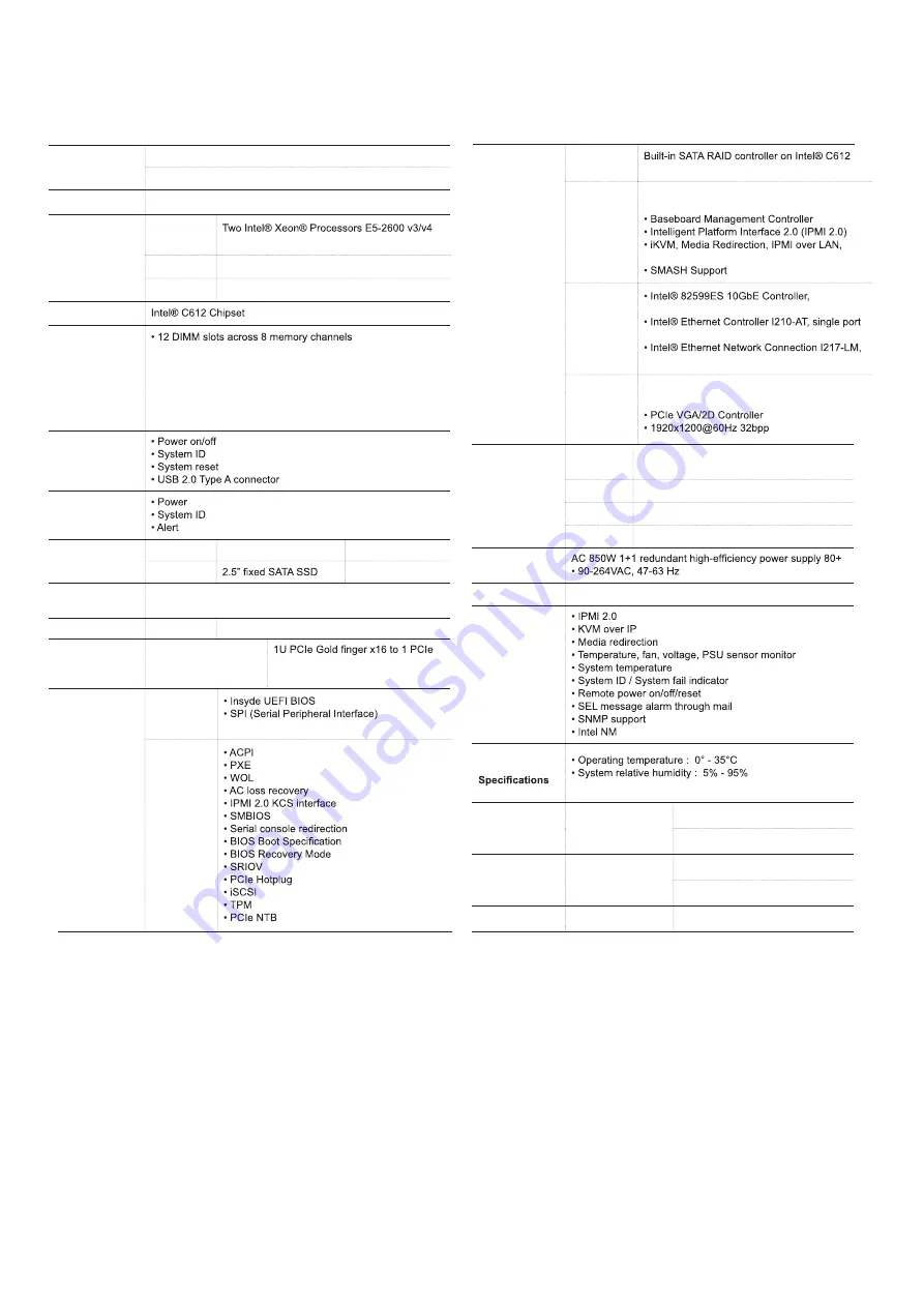
1.2 Specifications
Dimensions
(W x D x H)
mm : 438 x 787.4 x 44.4
inches : 17.2 x 31 x 1.75
Motherboard
AIC Server Board Phoenix
Processor
Processor
Support
product family
QPI Speeds
9.6 GT/s, 8.0 GT/s, 7.2 GT/s
Socket Type
Socket R3 (FCLGA2011-3)
Chipset Support
System Memory
(4 memory channels per CPU;
2 channels with 2DPC and 2 channels with 1DPC)
- 384GB DDR4 2133/1866 RDIMM DRx4
- 96GB DDR4 2133/1866 RDIMM SRx4
- 768GB DDR4 2133/1866 LRDIMM QRx4
- 1536GB DDR4 2133/1866 LRDIMM 3DS 8Rx4
Front Panel
LEDs
Drive Bays
External
2.5” hot swap PCIe SSD
10
Internal
2
Backplanes
5 x 2-port PCIe backplanes with dual SFF-8643
connectors on each
Expansion Slots
PCIe 3.0
1 x16, 1 x8
Riser Card
(included)
PSG-RC-PH1U-2N-110 x16, 1 PCIe x8 and 10 PCIe x4
(SFF-8643) for NVMe
System BIOS
BIOS Type
FLASH Interface
BIOS
Features
Rear I/O
LAN
2 x 10GbE SFP+
2 x RJ45
USB
2 x USB 3.0 Type A
VGA
1 x DB-15
Serial Port
1 x DB-9
Power Supply
System Cooling
6 x 40x56mm 21500/18000 rpm hot swap fan modules
System
Management
Environmental
non-condensing
Gross Weight
(w/ PSU & Rail)
kgs : 24
lbs : 53
Packaging
Dimensions
(W x D x H)
mm : 590 x 1130 x 273
inches : 23.2 x 44.5 x 10.7
Mounting
Standard
28" tool-less slide rail
On-board
Devices
SATA
Chipset with software RAID support
IPMI
Aspeed AST2400 Advanced PCIe Graphics &
Remote Management Processor
Serial over LAN
Network
Controllers
dual port, SFP+, PCIe v2.0 (5.0GT/s)
GbE controller, PCIe v2.1, 2.5 GT/s, x1
single port GbE, 1 Gbps
Graphics
Aspeed AST2400 Advanced PCIe Graphics &
Remote Management Processor
Содержание SB122A-PH
Страница 1: ...SB122A PH Storage Server Barebone User s Manual UM_SB122A PH_v 3_052918...
Страница 12: ...4 SB122A PH User s Manual Chapter 1 Product Features Front Panel...
Страница 55: ...Chapter 5 BMC Configuration Settings SB122A PH User s Manual 47 Step 3 Type in the subnet mask address...
Страница 67: ...Chapter 6 Hardware Specification SB122A PH User s Manual 6 2 Riser Card 6 2 1 Riser Card...
Страница 69: ...Chapter 6 Hardware Specification SB122A PH User s Manual 6 2 3 Internal Connectors Jumpers Power Connector J1...
Страница 70: ...Chapter 6 Hardware Specification SB122A PH User s Manual 6 3 Drive Slot Map...


