background image


20 


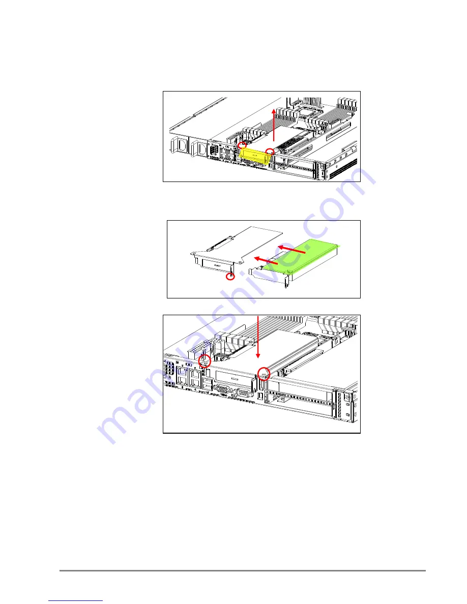
2.6.2 Install an External Expansion Card to the Riser Card (Low-profile) 


1.  Remove two screws on top of the bracket holder and twist out the metal 

plate to insert expansion card I/O ports. 


2. Connect the expansion card into the riser card slot which is located under the 

bracket holder. Secure it with one screw. 


3. Secure the bracket back with the screws to fix the expansion card. 


Содержание GB109-CT

Страница 1: ...GB109 CT General Purpose Server Barebone User s Manual Document Number MAN 00102 A GB109 CT General Purpose Server Barebone User s Manual Document Number MAN 00102 A...

Страница 2: ...Fans 21 2 8 Power Supply 22 2 8 1 Removing or Replacing the Power Supply Module 22 2 9 Fan Duct 22 1 Contents Contents 1 Safety Information 3 About This User s Manual 4 Chapter 1 Product Introduction...

Страница 3: ...out AIC products and is not to be disclosed or used except in accordance with applicable agreements 2 Contents 2 9 1 Installing the Fan Duct 22 Chapter 3 Motherboard Settings 23 3 1 Motherboard Layout...

Страница 4: ...acle Use of this type of adapter may result in risk of electric shock and or damage to this product 3 Safety Information When installing operating or performing maintenance on this equipment basic saf...

Страница 5: ...Hardware Setup Motherboard Settings BIOS Configuration and Settings BMC Configuration and Settings 4 About This User s Manual This document provides a detailed description of the GB109 CT including T...

Страница 6: ...Screw Kit 1 x Internal SAS to SAS Cable 2 x Internal SATA to SATA Cables 1 x 28 Rail 2 x Heatsinks 5 Chapter 1 Product Introduction 1 1 General Information GB109 CT a 1U 4bay General Purpose Barebone...

Страница 7: ...P with SGPIO support System BIOS BIOS Type AMI BIOS SPI Serial Peripheral Interface FLASH Interface 6 1 2 System Specifications Dimensions with chassis ears protrusions W x D x H mm 482 6 x 711 2 x 44...

Страница 8: ...ndition 0 10K feet Storage Temperature 20 60 C System Relative Humidity 5 to 95 38 C non condensing 7 BIOS Features ACPI 1 0 2 0 3 0 PXE 2 0 WOL AC loss recovery IPMI KCS interface SMBIOS 2 0 Serial c...

Страница 9: ...h efficiency 650W 1 1 hot swap redundant power supplies 80 4 x RJ45 ports DB 9 serial port VGA port 8 1 3 Front View of GB109 CT 1 4 Rear View of GB109 CT LED Icon Color Behavior Controls Icon System...

Страница 10: ...pansion Slots System Fans SAS SATA Backplane Hot swap HDD trays Rear I O 2 5 Internal Drive Bracket 9 1 5 Top View of GB109 CT The barebone server includes the basic components shown below Castor Moth...

Страница 11: ...er from chassis 2 1 2 Removing the Fan Duct 1 Release three screws to remove the fan duct 6 32 6 32 10 Chapter 2 Hardware Setup This section demonstrates maintenance procedures in replacing a defectiv...

Страница 12: ...processor hold the processor only by its edges to avoid touching the contacts Load lever Load plate 11 2 2 Central Processing Unit CPU 2 2 1 Installing the CPU 1 Press the load lever to release the lo...

Страница 13: ...sed against them Please keep the socket protective cover on when processor is not installed Cutouts 12 4 Align the processor cutouts against the socket notches 5 Close the load plate load lever Press...

Страница 14: ...mal paste to the bottom of heatsink and spread in an even thin layer before installing the heatsink 13 2 2 2 Installing the CPU Heatsink To install the CPU heatsink 1 Place the heatsink on top of the...

Страница 15: ...1 CH0 8 DIMMs CPU0 DIMM 0 CPU1 DIMM 0 CPU0 DIMM 0 CPU1 DIMM 0 CPU0 DIMM 0 DIMM 1 CPU1 DIMM 0 DIMM 1 14 2 3 System Memory This server board supports up to twelve DDR3 800 1066 1333 Registered ECC SDRAM...

Страница 16: ...press down until it snaps into place Note DIMM notch and socket bump must align as shown DIMM notch 15 CH2 CH1 CH0 10 DIMMs CPU0 DIMM 0 CPU1 DIMM 0 CPU0 DIMM 0 DIMM 1 CPU1 DIMM 0 DIMM 1 CPU0 DIMM 0 DI...

Страница 17: ...when its front edge aligns with the bay edge 5 Repeat Steps 1 through 4 to install the rest of HDDs 16 2 4 Drive Bays 2 4 1 Installing or Replacing 3 5 Hot swap SAS SATA HDD 1 Release a drive tray by...

Страница 18: ...HDD into the pins 3 Tighten the thumb screw 4 Repeat Steps 1 through 4 to install the rest of HDDs 17 2 4 2 Installing or Replacing 2 5 Internal SAS SATA HDD 1 Release the thumb screw Pull the bracke...

Страница 19: ...Riser for Castor RISER CARD DIAGRAM M H 4 M H 3 M H 2 M H 1 J2 A 1 A 11 A 12 A 49 Slot Bandwidth X8 18 2 5 Riser Card 1 RISER CARD PN PSG CODE DESCRIPTION PSG RC AQ1U 20 111 PE1U04 1U Gold finger PCIe...

Страница 20: ...with the two screws and card retainer to fix the expansion card Card retainer Card retainer bracket 19 2 6 Expansion Slot 2 6 1 Install an External Expansion Card to the Riser Card 1 Remove two screws...

Страница 21: ...holder Secure it with one screw 3 Secure the bracket back with the screws to fix the expansion card 20 2 6 2 Install an External Expansion Card to the Riser Card Low profile 1 Remove two screws on top...

Страница 22: ...ely connecting the top hooks Fan cable Caution shut down the system before removing the system fans 21 2 7 System Fans 2 7 1 Removing or Replacing the System Fans 1 Disconnect the fan cable 2 Remove t...

Страница 23: ...1 Installing the Fan Duct 1 Put the fan duct on the fan bar and secure with three screws 6 32 6 32 22 2 8 Power Supply 2 8 1 Removing or Replacing the Power Supply Module 1 Hold the PSU lever and fir...

Страница 24: ...HEADER J5 1 LAN LED J19 4 KB MS J7 2 DEBUG PORT J8 5 LCM CONN J19 3 FRONT PANEL J15 6 BUZZER 5V J18 23 Chapter 3 Motherboard Settings This section describes the jumper settings of AIC s Castor PSG M C...

Страница 25: ...ET OFF NORMAL J29 CLEAR CMOS 1 3 1 2 NORMAL 2 3 CLEAR OPEN INVALID SW1 PCIe Strapping Configuration 24 3 2 1 Jumpers J14 VGA DISABLE 1 2 1 2 DISABLE OFF ENABLE J21 AST ARM 1 2 1 2 DISABLE OFF ENABLE J...

Страница 26: ...5 MS_DATA 6 GND J9 LCM CONN 1 POWER_BTN 2 RESET_BTN 3 TX 4 RX 5 GND J18 BUZZER 5V 1 BUZZER 2 BUZZER 25 3 2 2 Internal Connectors JP1 BMC DEBUG 1 3 1 Tx 2 Rx 3 GND J6 UART COM2 9 NC 10 GND 7 RI 8 DTR 5...

Страница 27: ...AN8_TACH 3 FAN1_TACH 4 PWM1 5 FAN2_TACH 6 PWM2 7 FAN3_TACH 8 PWM3 9 FAN4_TACH 10 PWM4 11 GND 12 GND 26 3 2 3Internal Connectors continue J46 BMC GPIO 5 BMC_GPIOE6 6 BMC_GPIOB2 4 BMC_GPIOB7 3 BMC_GPIOE...

Страница 28: ...GND 13 SYS FLT LED 14 FP NMI BTN 15 SYS FLT LED 16 GND 17 SB SMB DATA 18 5VSB 19 SB SMB CLK 20 GND 27 3 2 4 Internal LEDs J19 LAN LED LED ON LAN LINK LED BLINK ACTIVE 1 GbE1 LED 2 GbE1 LED 3 GbE2 LED...

Страница 29: ...end in an 0 Caution When Quiet Boot IS enabled OEM LOGO WILL BE displayed INSTEAD OF POST MESSAGES 28 Chapter 4 BIOS Configuration and Settings 4 1 BIOS Setting 1 Press DEL to run the setup procedure...

Страница 30: ...the BIOS Version 4 Load Optimal Default setting 5 Save the setting and exit the BIOS setup utility 29 3 Identify the BIOS Version 4 Load Optimal Default setting 5 Save the setting and exit the BIOS s...

Страница 31: ...tem while the BIOS is updating Caution The system will reboot after exiting the BIOS update Utility 30 4 2 Updating BIOS 1 AFUDOS is a BIOS update utility with command line interface that works in DOS...

Страница 32: ...se the BIOS setup 1 BIOS SETUP Advance IPMI configuration Set LAN configuration BMC management port 31 Chapter 5 BMC Configuration and Settings Insert BMC IP LAN into the BMC LAN port There are two me...

Страница 33: ...IP address Set IP static Note type 1 for selecting static IP mode or type 2 for selecting DHCP mode 32 2 Input IP address Set IP static Note type 1 for selecting static IP mode or type 2 for selecting...

Страница 34: ...33 3 Input subnet mask address 33 3 Input subnet mask address...

Страница 35: ...tting 3 Input IP address Note type 1 for selecting static IP mode or type 2 for selecting DHCP mode 34 5 2 Method 2 Use a Dos tool Syscheck 1 Type sc lanset 2 Modify IP setting 3 Input IP address Note...

Страница 36: ...use 5 Finish BMC IP configuration Note Type sc exe langet command to obtain BMC IP and MAC address 35 4 Input submask address Below IP address is an example using a default IP setting User is allowed...

Страница 37: ...an be changed after login Note This feature works with JAVA 6 runtime installed console environment 36 5 3 Connect to BMC Below IP address is an example using default IP setting User is allowed to cha...

Страница 38: ...Sensor Readings 5 Configuration Please refer to AIC BMC User Guide for more information on AIC BMC 37 3 Information of ASTER firmware 4 Server Health Sensor Readings 5 Configuration Please refer to A...

Страница 39: ...de to absolute For Linux OS environment set mode to relative 6 Remote Control Environmental setting 38 Mouse Mode setting For Windows OS environment set mode to absolute For Linux OS environment set m...

Страница 40: ...CORD 5 SECONDS AND THEN PLUG AC POWER CORD TO RESET BMC THEN UPDATED NEW FUNCTION CAN WORK PROPERLY 39 Press ALT M for local and remote OS mouse control switching 5 4 Updating BMC Firmware 1 Boot to t...

Страница 41: ...CORD 5 SECONDS AND THEN PLUG AC POWER CORD TO RESET BMC THEN UPDATED NEW FUNCTION CAN WORK PROPERLY 40 5 5 Updating BMC Configuration 1 Boot to DOS MS DOS or Free DOS is workable 2 Enter BMC config fi...

Страница 42: ...Tel 31 30 6386789 Fax 31 30 6360638 Email Technical Support support aicipc com Http www aicipc com 41 Chapter 6 Technical Support TAIWAN Tel 886 3 313 8386 Fax 886 3 313 8377 Email Technical Support...

Страница 43: ...42 Note 42 Note...

Отзывы: