


----EN
EN
EN
EN----
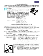
2.3 INSTALLATION SITE
Failure to install dryer in the proper ambient conditions will affect the dryer’s ability to condense
refrigerant gas. This can cause higher loads on the compressor, loss of dryer efficiency and
performance, overheated condenser fan motors, electrical component failure and dryer failure due to
the following: compressor loss, fan motor failure and electrical component failure. Failures of this type
will affect warranty considerations.
Do not install dryer in an environment of corrosive chemicals, explosive gasses, poisonous gasses;
steam heat, areas of high ambient conditions or extreme dust and dirt.
In case of fire, use an approved fire
extinguisher, water is not an acceptable
means in cases of fire.
Minimum installation requirements
:
•
Select a clean dry area, free from dust, and
protected from atmospheric disturbances.
•
The supporting area must be smooth, horizontal
and able to hold the weight of the dryer.
•
Minimum ambient tempe34 °F (+1 °C).
•
Maximum ambient tempe120°F (50°C),
•
Allow at least a clearance of 40in (1m) on each
side of the dryer for proper ventilation and to
facilitate eventual maintenance operations.
The dryer does not require attachment to the floor
surface; however installations where the unit is
suspended require an attachment to the hanging
apparatus.
40in - 1
m
4
0
in
-
1
m
40in - 1
m
40in
- 1m
20-50
1
in
-
2
6
m
m
1/2in - 14mm
3/8in - 10mm
14in - 354mm
L
G
T
0
0
1
2
1
.1
/4
in
3
0
m
m
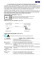
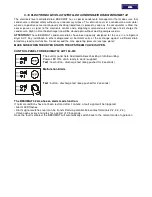
2.4 INSTALLATION LAYOUT
1
Air compressor
2
Condensate separator
3
Line filter (min. 20 micron)
4
By-pass group
5
AHT Dryer
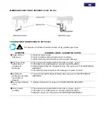
Aftercooler
Pre-Filter (FTP Series - 3 micron)
Alu-Dry Module
6
Compressed air tank
7
Final filter
1
- A -
- B -
2
8
3
8
6
8
8
8
5
5.1
5.2
5.3
IN
OUT
8
7
4
6
8
7
8
2
3
1
8
8
5
8
8
5.3
OUT
5.2
5.1
IN
4
8
Condensate drain
In case of heavily polluted inlet air (ISO 8573.1 class 4.-.4 or worse quality), we recommend the additional
installation of a pre-filter (20 micron minimum) to prevent a clogging of the heat exchanger.
Type A
installation is suggested when the compressor operates at reduced intermittence and the total consumption
equals the compressor flow rate.
Type B
installation is suggested when the air consumption can consistently change with peak values highly exceeding
the flow rate of the compressor. The capacity of the tank must be sized in order to compensate eventual instantaneous
demand conditions (peak air consumption).
Содержание 20-350
Страница 29: ...7 1 1 AHT 20 50 AC 7 1 2 AHT 75 AC 7 1 3 AHT 100 150 AC ...
Страница 30: ...7 1 4 AHT 200 250 AC 7 1 5 AHT 300 350 AC ...
Страница 31: ...7 2 1 AHT 20 50 ...
Страница 32: ...7 2 2 AHT 75 ...
Страница 33: ...7 2 3 AHT 100 ...
Страница 34: ...7 2 4 AHT 150 ...
Страница 35: ...7 2 5 AHT 200 250 ...
Страница 36: ...7 2 6 AHT 300 350 ...
Страница 41: ...NOTE ...
Страница 42: ...NOTE ...
Страница 43: ...NOTE ...
Страница 44: ...GRAMAGLIA GO ...


