


----EN
EN
EN
EN----
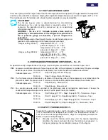
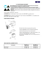
5.11 HOT GAS BY-PASS VALVE
This valve injects part of the hot gas (taken from the discharge side of the compressor) in the pipe between the evaporator
and the suction side of the compressor, keeping the evaporation temperature/pressure constant at approx. 36°F (+2 °C).
This injection prevents the formation of ice inside the dryer evaporator at every load condition.
A
4 mm
5/32 in.
+
-
ADJUSTMENT
The hot gas by-pass valve is adjusted during the manufacturing
testing phase. As a rule no adjustment is required; anyway if it is
necessary the operation must be carried out by an experienced
refrigeration engineer.
WARNING : the use of ¼” Schrader service valves must be
justified by a real malfunction of the refrigeration system. Each
time a pressure gauge is connected, a part of refrigerant is
exhausted.
Without compressed air flow through the dryer, rotate the adjusting screw
(position A on the drawing) until the following value is reached:
Hot gas setting (R134.a) : temperature 33°F (+1 / -0 °F)
pressure 29 psig (+1.5 / -0 psi)
temperature 0.5°C (+0.5 / -0 °K)
pressure 2.0 barg (+0.1 / -0 bar)
Hot gas setting (R404A) :
temperature 33°F (+1 / -0 °F)
pressure 75.4 psig (+1.5 / -0 psi)
temperature 0.5 °C (+0.5 / -0 °K)
pressure 5.2 barg (+0.1 / -0 bar)
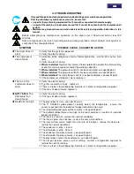
5.12 REFRIGERANT PRESSURE SWITCHES P
A
- P
B
- P
V
As operation safety and protection of the dryer a series of pressure switches are installed in gas circuit.
PB :
Low-pressure controller device on the pushing side (carter) of the compressor, is enabled only if the pressure drops
below the pre-set value. The values are automatically reset when the nominal conditions are restored.
Calibrated pressure : R 404 A
Stop 14.5 psig - Restart 72.5 psig
R 404 A
Stop 1.0 barg - Restart 5.0 barg
PA :
This high-pressure controller device, located on the pushing side on the compressor, is activated when the
pressure exceeds the pre-set value. It features a manual-resetting button mounted on the controller itself.
Calibrated pressure : R 404 A
Stop 464 psig - Manual reset
R 404 A
Stop 32 barg - Manual reset
PV :
Fan control pressure switch is placed at the discharge side of refrigeration compressor. It keeps the
condensation temperature/pressure constant within preset limits (Air-Cooled).
Calibrated pressure : R 134.a
Start 160 psig (117°F) - Stop 116 psig (97°F) - Tolerance
±
15 psi
R 134.a
Start 11 barg (47°C) - Stop 8 barg (36°C) - Tolerance
±
1 bar
R 404 A
Start 290 psig (113°F) - Stop 232 psig (97°F) - Tolerance
±
15 psi
R 404 A
Start 20 barg (45°C) - Stop 16 barg (36°C) - Tolerance
±
1 bar
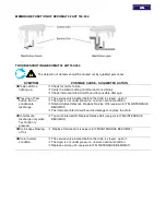
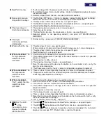
5.13 SAFETY THERMO-SWITCH T
S
To protect the operating safety and the integrity of the dryer, a thermo-switch
(TS) is installed on the refrigerant gas circuit. The thermo-switch sensor, in
case of unusual discharge temperatures, stops the refrigerating compressor
before it is permanently damaged.
1
2
P
Q
S
0
0
0
5
T
S
:
Manually reset the thermo-switch only after the nominal operating
conditions have been restored. Unscrew the relative cap (see pos.1 in
the figure) and press the reset button (see pos.2 in the figure).
Содержание 20-350
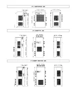
Страница 29: ...7 1 1 AHT 20 50 AC 7 1 2 AHT 75 AC 7 1 3 AHT 100 150 AC ...
Страница 30: ...7 1 4 AHT 200 250 AC 7 1 5 AHT 300 350 AC ...
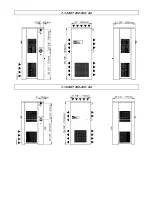
Страница 31: ...7 2 1 AHT 20 50 ...
Страница 32: ...7 2 2 AHT 75 ...
Страница 33: ...7 2 3 AHT 100 ...
Страница 34: ...7 2 4 AHT 150 ...
Страница 35: ...7 2 5 AHT 200 250 ...
Страница 36: ...7 2 6 AHT 300 350 ...
Страница 41: ...NOTE ...
Страница 42: ...NOTE ...
Страница 43: ...NOTE ...
Страница 44: ...GRAMAGLIA GO ...


