


40
VI. Water Piping and Trim
A. Factory Supplied Piping and Trim (continued)
b. Install close nipple into tee branch. Then, screw
the assembly into boiler left side ¾ in. front
tapping, making sure tee run outlet is in vertical
plane and parallel to boiler side.
c. Install the ¾ in. NPT x 12 in. black nipple into
tee top run outlet.
d. Mount ¾ in. FPT x 1 in. FPT safety relief valve
onto 12 in. nipple.
e. Install drain valve into tee bottom run outlet.
f. Locate and remove 2 in. NPT steel coupling,
(2) 2 in. NPT x 2-1/2 in. long black nipples, 2
in. x 2 in. x ½ in. NPT black tee, 2 in. x 2 in. x
1 in. NPT black tee, packaged flow switch with
paddles, and temperature & pressure gauge.
g. Mount 2 in. NPT coupling onto 2 in. MPT boiler
supply tapping (see Figure 1C). Then, install 2
in. NPT x 2-1/2 in. long black nipple into the
coupling outlet. Attach 2 in. x 2 in. x ½ in. tee
onto the nipple opposite end, making sure ½ in.
branch outlet is in horizontal plane and facing
the boiler front.
h. Install temperature & pressure gauge into the tee
branch.
i. Install second 2 in. NPT x 2½ in. long nipple into
2 in. x 2 in. x 1/2 in. NPT tee run.
j. Mount 2 in. x 2 in. x 1 in. NPT black tee onto the
nipple, making sure tee 1 in. NPT branch outlet
is oriented upward.
k. Remove flow switch and paddles from packaging
carton. Also see/follow Taco Instruction Sheet
for Flow Switch Kit (supplied with flow switch)
for specific details.
l. Select paddle stamped “1” for APX825.
m. Attach paddle to flow switch stem using supplied
machine screw.
n. Apply pipe dope to the switch-threaded brass-
bushing end. Then, mount the switch threaded
end with the attached paddle into 2 in. x 2 in.
x 1 in. NPT tee branch and tighten such that
distance between bottom of switch housing and
top of tee branch is approximately 1-11/16 in.
(43 mm). Insure the switch paddle is positioned
Boiler
Model
Supply
Connection
(in.)
Return
Connection
(in.)
ΔT
= 35°F
ΔT
= 30°F
ΔT
= 25°F
ΔT
= 20°F
Minimum
Required
Flow (GPM)
Boiler
Head
Loss (ft.)
Required
Flow
(GPM)
Boiler
Head Loss
(ft.)
Required
Flow
(GPM)
Boiler
Head Loss
(ft.)
Maximum
Required
Flow
(GPM)
Boiler
Head
Loss (ft.)
APX425
1-1/2
1-1/2
21.5
6.1
25.1
7.9
30.2
10.8
37.7
15.9
APX525
1-1/2
1-1/2
27.1
6.9
31.7
8.9
38.0
12.1
47.5
17.6
APX625
2
2
33.9
4.7
39.6
6.1
47.5
8.4
59.4
12.4
APX725
2
2
39.4
6.0
45.9
7.9
55.1
10.9
68.9
16.1
APX825
2
2
43.4
12.1
50.7
15.5
60.8
20.9
76.0
30.0
Notes: Required Flow = Output*1000/(500*ΔT), where flow rate is in GPM, output is in MBH, and ΔT is in °F
Outputs for specific boiler models are provided in Table 2.
See also Tables 13 A and 13B for near boiler piping sizing.
Using boiler antifreeze will result in increased fluid density and may require larger circulators.
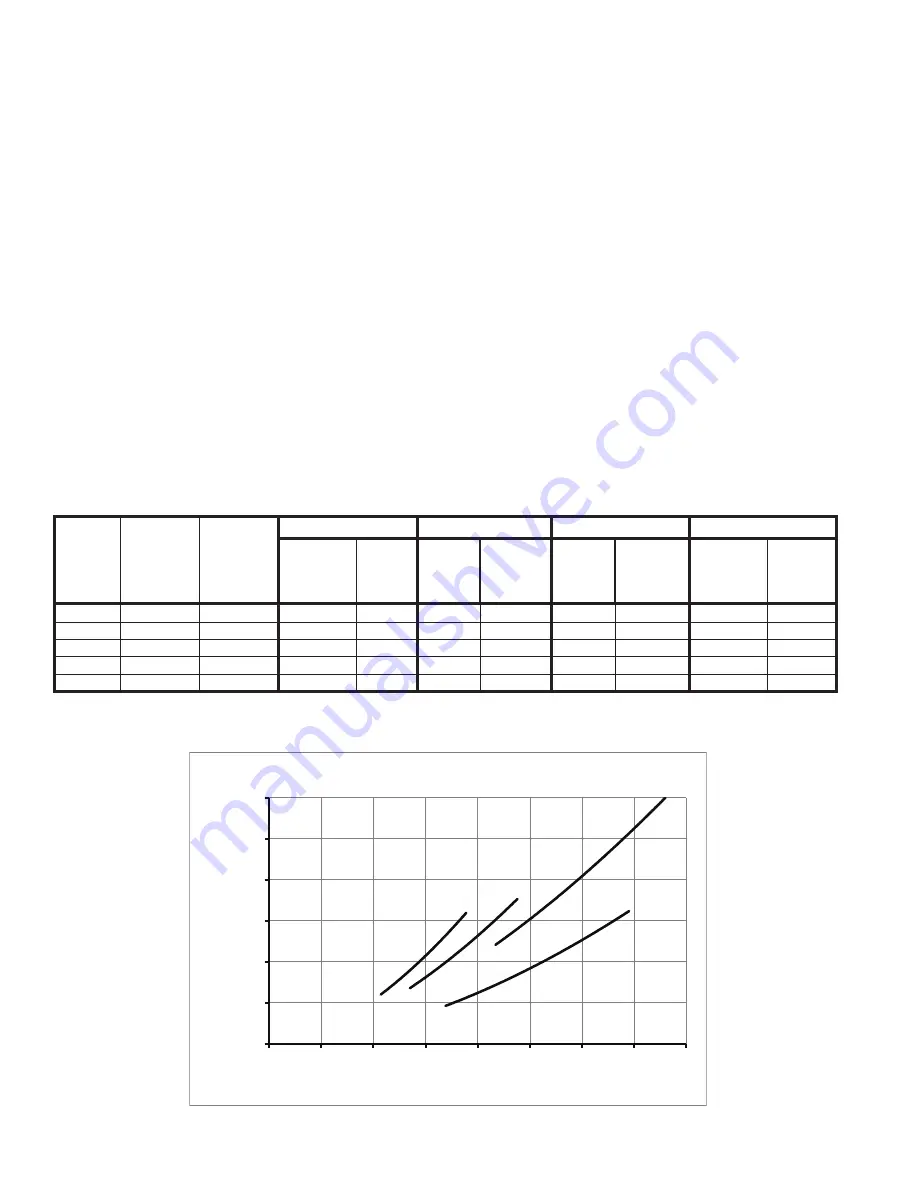
Table 12: Flow Range Requirement Through Boiler
0
5
10
15
20
25
30
0
10
20
30
40
50
60
70
80
Head
Loss
(ft.)
Water Flow Rate (GPM)
Boiler Head Loss
425
525
825
625/725
Содержание APEX
Страница 6: ...6 I Product Description Specifications and Dimensional Data continued Figure 1A Apex Model APX425 ...
Страница 7: ...7 Figure 1B Apex Model APX525 I Product Description Specifications and Dimensional Data continued ...
Страница 9: ...9 I Product Description Specifications and Dimensional Data continued Figure 1D Apex Model APX825 ...
Страница 57: ...57 VIII Electrical continued Figure 26 Ladder Diagram ...
Страница 58: ...58 VIII Electrical continued ...
Страница 59: ...59 Figure 27 Wiring Connections Diagram VIII Electrical continued ...
Страница 68: ...68 IX System Start up continued Apex Series Operating Instructions Figure 34 Operating Instructions ...
Страница 105: ...105 ...
Страница 109: ...109 XIII Repair Parts continued APX625 APX725 and APX825 APX825 shown ...
Страница 112: ...112 XIII Repair Parts continued APX425 and APX525 ...
Страница 114: ...114 XIII Repair Parts continued APX625 APX725 and APX825 ...
Страница 122: ...122 ...
Страница 123: ...123 ...


