


12
Specifications and Need
-
to
-
Know Information
alphaTIG 203Xi
cumstances should you attempt to modify or make unauthorized
changes to the welder or its programming. To do so will void the war-
ranty.
HF Point Gap Maintenance
This unit is equipped with adjustable high frequency points
that generate the High Frequency Voltage to create the
touchless HF start of the unit. Occasionally, adjustment
may be needed, particularly in the first few months of oper-
ation, and periodically thereafter. This is a simple adjustment after
you
’
ve done it once or twice. The point gap should be set between
0.029”
to
.040”
for best operation. The target point gap should be
between
.030”
and
.035”.
A point gap that is too small may cause
weak starts. A point gap that is too wide may cause electrical inter-
ference with surrounding equipment and electronic items.
The location of the points can be identified by quickly pressing the
torch switch/foot pedal while looking up through the front vents of
the welder. The points should arc briefly. If they do not, they may
only need adjustment or cleaning. (But if after adjustment they do
not fire, contact Ahp technical support at the number listed on the
front of this manual.) If you do not see the arc location, look up and
to the left of the unit. There will be a small board with a brass and
black plastic holder along with carbon contacts in them. They will be
located on a small square board with a couple rows of small capaci-
tors and a coil/transformer on the same board.
To gain access to the points and adjust them, follow steps
1
–
6
on
the previous page. You will need a small jeweler
’
s or mechanic
’
s
screwdriver, and small ignition wrench and a feeler gauge to set the
points. Do not overtighten the jam nut securing the adjustment
screw. Hold the screwdriver in place on the screw while tightening
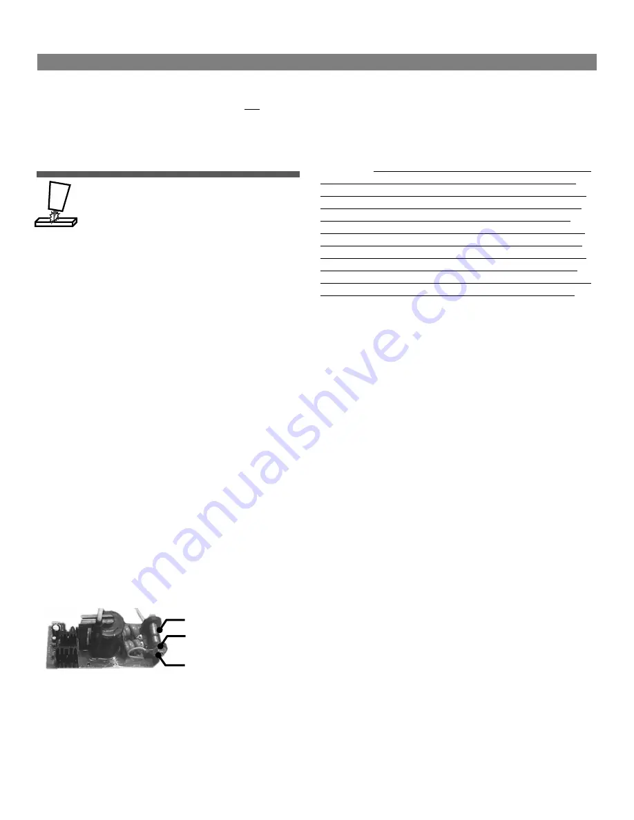
the jam nut with an ignition wrench. See the image below.
The board in the image below is shown inverted for demonstration
purposes and is removed from the unit. Removal is not necessary. The
points will be in the
“
hanging
”
position and can be adjusted through
the left side of the machine. (Whole board is not pictured.)
For more detailed written and illustrated directions on how to locate
and adjust the point gap, contact Ahp technical support.
NOTICE:
Point Gap adjustment is a part of regular maintenance and
is a normal responsibility of the customer. Point gap adjustment and
normal cleaning/maintenance does not fall under the warranty terms
for this welder. If you have any issues or questions concerning point
gap adjustment, call or contact Ahp tech support before attempting
the adjustment. The HF system used in this unit is only used for
starting the arc. They do not stay on while welding in DC or in AC.
They have no effect other than arc starting efficiency. Inverters
switch so quickly in AC that HF is not needed to maintain a stable arc.
IMPORTANT:
Do not needlessly adjust the point gap in order to try to
resolve operational issues not related directly to arc starting. Arc
starting is the only purpose of the HF points inside this unit. Before
assuming you have an HF starting issue, check the work clamp, the
work clamp cable and connections under the rubber boot on the
DINSE connector to make sure the connections are tight, and corro-
sion free. Connect the work clamp directly to a freshly ground spot
on the work piece and attempt to weld before assuming you have an
HF point gap issue. Also make sure polarity is correct. Most com-
monly, a poor connection to the work piece, corrosion or wrong polar-
ity is the cause of poor arc starting rather than a point gap issue.
Other items that may also cause poor arc starting:
•
Wrong shielding gas, or not enough flow.
•
Too much gas flow creating turbulence.
•
Welder is too close to the weld area and fans are blowing gas
coverage off weld. Move to 6
-
8 feet away.
•
Dirty or contaminated metal Preclean aluminum with Stainless
brush or special aluminum grinding wheel. Decontaminate with
acetone or aluminum cleaner made specifically for welding Alu-
minum. Grind steel with hard stone on grinder. Refrain from
using flap disks which often polish the mill scale rather than
remove it.
•
Too long of an arc gap between tungsten and metal.
•
Too much stick
-
out of the Tungsten, not enough shielding gas
flowing around Tungsten.
•
No Pre
-
Flow. Set to .3 to .5 Seconds.
•
Wrong Tungsten. Use Lanthanated or Ceriated Tungsten for all
processes. Do not use pure, or zirconiated types of Tungsten.
Use caution when trying new or proprietary
“
blends
”.
Often
these have poor quality control.
•
Work Clamp is not connected directly to what is being welded.
•
Work clamp, cable, or connector is corroded or bad. Check all
connections, including where the cable attaches to the DINSE
type connector. (You must pull rubber boot back).
•
Dirty Tungsten. This is often indicated by a green flare or spit-
ting while starting the arc or while welding.
HF Point Gap Location
Locking Nut
Adjustment Screw
Содержание alphaTIG 203Xi
Страница 32: ...32 ...


