background image

Installation & Operation Manual                                                                                        Merlin GDP2X 


AGSGDP2X - IOM Iss: 3   03-20


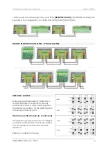
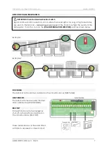
12-24V power and data supply from your GDP2X [DETECTOR CHAIN] to [DETECTOR X CHAIN] can 
be wired in any configuration. i.e. [IN/IN] [OUT/OUT] [IN/OUT] [OUT/IN] etc. 


MULTIPLE DETECTOR CHAIN SYSTEM - TYPICAL EXAMPLES 


DETECTOR – ID SETUP. 
 
When wiring multiple model ‘X’ detectors to 
the GDP2X range it is important to identify 
each detector and in which monitoring zone 
the detector is located - for the GDP2X system 
to receive and display data.  
 
ID switches are fitted to detector circuit boards.  
 
The diagram opposite shows how to configure 
switches for each detector and is also printed 
onto the detector circuit boards for quick 
reference. 
 
Refer to your detector manual. 

Содержание Merlin GDP2X

Страница 1: ...etain for future use American Gas Safety provide a range of detection panels which can be used in many applications such as factories car parks shopping malls and most commonly for this model boiler h...

Страница 2: ...ing the GDP2X 5 Settings Switch 8 Settings Menu 9 Settings Options Explained 9 Factory Set Condition 9 Trouble Shooting 9 Specification 10 OPERATION 11 First Power Up 11 Main Screen 11 Zone Screens 11...

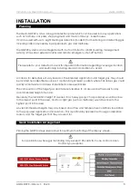
Страница 3: ...and areas of identified consequential risk The composition of the target gas and its density relative to air are used as the basis for any recommended height of sensors Generally the installation hei...

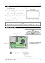
Страница 4: ...e four screw holes located on the back of the enclosure to the wall Ensure the wall surface is flat to prevent base distortion 3 After executing the mounting and the connections replace the front cove...

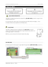
Страница 5: ...ot on the AGS Logo VALVE OUTPUT 100 120V AC electrical power supplied from the VALVE OUT connector using a 3 core cable can be connected to a gas solenoid valve which can shut the gas supply on alarm...

Страница 6: ...AL EXAMPLES DETECTOR ID SETUP When wiring multiple model X detectors to the GDP2X range it is important to identify each detector and in which monitoring zone the detector is located for the GDP2X sys...

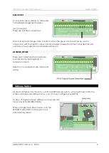
Страница 7: ...P Connections for remote emergency shut off or stop buttons is detailed on the circuit board as EM STOP These terminals are volt free and fitted with links to represent a closed circuit DETECTOR Chain...

Страница 8: ...ces and controls such as purge fans and audible alarms etc SOUNDER STROBE There are connections for an external sounder alarm strobe lighting to activate on alarm Refer to your sounder strobe manual f...

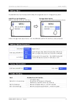
Страница 9: ...NS Explanation BMS relay ON OFF for Gas Error Gas changes relay state with gas valve status only Error changes relay state upon all alarm messages Auto Start ON OFF In the event of a power loss the GD...

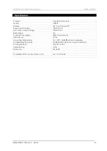
Страница 10: ...tage 100 120V AC Gas Valve Output Voltage 100 120V AC BMS Output 3A Current Consumption 20W max full load Internal Fuse 3 15A Operating Temperature 32 122 F 30 85 RH Non Condensing Audible Alarm Buzze...

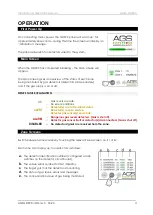
Страница 11: ...OK o Gas levels are safe o No error conditions ALERT o Detector s are in Pre Alarm status o Detector s require service o Detector gas sensor s end of life ALARM o Dangerous gas levels detected Gas is...

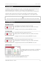
Страница 12: ...will silence the audible alarm buzzer Investigate and rectify the issue before RESETTING the panel FIRE PANEL ALARM The fire alarm panel has reached alarm status Pressing MUTE on the GDP2X will silenc...

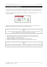
Страница 13: ...or ID in alarm in the top left hand corner DO carefully remove any accumulated dust from the outer enclosure once a month NEVER use detergents or solvents to clean your detectors this may permenantly...

Страница 14: ...g safely If the bump test results are not within the acceptable range the gas detector must not be used until a full calibration has been conducted Bump testing has a number of benefits for the end us...

Страница 15: ...urchaser that this product will be free of defects in material and workmanship for a period of three 3 years from date of purchase The manufacturer s liability hereunder is limited to replacement of t...

Страница 16: ...the system owner or system user Date of Installation Installation Location Organisation Stamp Signature of the installer CONTACT US AGS Head Office Tel 727 608 4375 Fax 727 538 4237 info americangassa...

Отзывы: