Service Guide E8364-90038
2-3
PNA Series Microwave Network Analyzers
General Product Information
E8362C, E8363C, E8364C
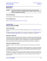
Maintenance
Maintenance
WARNING
To prevent electrical shock, disconnect the analyzer from the mains source before
cleaning. Use a dry cloth or one slightly dampened with water to clean the external case
parts. Do not attempt to clean internally.
Physical Maintenance
Clean the cabinet, including the front panel, using a dry or slightly damp cloth only.
Electrical Maintenance
Refer to
“Review the Principles of Connector Care” on page 3-5
.
Analyzer Options Available
Options as Upgrades
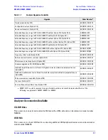
The options described in this section can be ordered as upgrades. Refer to
“Analyzer Upgrades Available” on
page 2-6
.
Individual upgrade kits are also available and can be ordered by part number. Refer to
“E8362C Upgrade Kits”
on page 6-85
and
“E8363C, E8364C Upgrade Kits” on page 6-85
for a complete list of available kits.
Option 010, Time Domain
An Option 010 analyzer can display the time domain response of a network or test device by calculating the
inverse Fourier transform of the frequency domain response. This calculation allows the Option 010 analyzer
to show the response of a test device as a function of time or distance. In time domain, the magnitude and
location of a discontinuity and the characteristics of individual transmission paths of a network or test
device can be determined. Time domain operation retains all the accuracy of active error correction.
Option 014, Configurable Test Set
An Option 014 analyzer can be configured to measure high-power devices and devices for high dynamic
range.
For a high-power measurement, external amplifiers and high power attenuators or isolators can be added to
complete the test setup. Test port output power up to 1 Watt (+30 dBm) can be applied to the device under
test (DUT). Additionally, there is an external reference input that allows the external amplifier’s frequency
response and drift to be ratioed out.
For high dynamic range measurements, front panel jumpers are moved to reverse the signal path through
one of the couplers, allowing for a 15 dB improvement in transmitted signal sensitivity in one direction only.
Jumpers are installed on both ports allowing the user to choose a measurement in either the forward or
reverse direction.
Содержание E8362C
Страница 11: ...Service Guide E8364 90038 1 1 1 Safety and Regulatory Information ...
Страница 21: ...Service Guide E8364 90038 2 1 2 General Product Information ...
Страница 33: ...Service Guide E8364 90038 3 1 3 Tests and Adjustments ...
Страница 81: ...Service Guide E8364 90038 4 1 4 Troubleshooting ...
Страница 137: ...Service Guide E8364 90038 5 1 5 Theory of Operation ...
Страница 171: ...Service Guide E8364 90038 6 1 6 Replaceable Parts ...
Страница 257: ...Service Guide E8364 90038 7 1 7 Repair and Replacement Procedures ...
Страница 341: ...Service Guide E8364 90038 8 1 8 General Purpose Maintenance Procedures ...
Страница 382: ...Index 20 Service Guide E8364 90038 Index ...

