Agilent Technologies E7401A Скачать руководство пользователя страница 1

Programmer’s Guide

Agilent Technologies EMC Series

Spectrum Analyzers

This guide documents firmware revision A.08.xx

This manual provides documentation for the following instruments:

E7401A (9 kHz - 1.5 GHz)

  E7402A (9 kHz - 3.0 GHz)
  E7403A (9 kHz - 6.7 GHz)

E7404A (9 kHz - 13.2 GHz)
E7405A (9 kHz - 26.5 GHz)

Manufacturing Part Number: E7401-90053

Supersedes: E7401-90028

Printed in USA

December 2001

© Copyright 

1999 - 2001 Agilent Technologies, Inc.

Содержание E7401A

Страница 1: ...08 xx This manual provides documentation for the following instruments E7401A 9 kHz 1 5 GHz E7402A 9 kHz 3 0 GHz E7403A 9 kHz 6 7 GHz E7404A 9 kHz 13 2 GHz E7405A 9 kHz 26 5 GHz Manufacturing Part Number E7401 90053 Supersedes E7401 90028 Printed in USA December 2001 Copyright 1999 2001 Agilent Technologies Inc ...

Страница 2: ...ered to could result in injury or loss of life Do not proceed beyond a warning note until the indicated conditions are fully understood and met CAUTION Caution denotes a hazard It calls attention to a procedure that if not correctly performed or adhered to could result in damage to or destruction of the instrument Do not proceed beyond a caution sign until the indicated conditions are fully unders...

Страница 3: ...duct damage Warranty This Agilent Technologies instrument product is warranted against defects in material and workmanship for a period of three years from date of shipment During the warranty period Agilent Technologies will at its option either repair or replace products which prove to be defective For warranty service or repair this product must be returned to a service facility designated by A...

Страница 4: ...PURPOSE Should Agilent have a negotiated contract with the User and should any of the contract terms conflict with these terms the contract terms shall control EXCLUSIVE REMEDIES THE REMEDIES PROVIDED HEREIN ARE BUYER S SOLE AND EXCLUSIVE REMEDIES AGILENT TECHNOLOGIES SHALL NOT BE LIABLE FOR ANY DIRECT INDIRECT SPECIAL INCIDENTAL OR CONSEQUENTIAL DAMAGES WHETHER BASED ON CONTRACT TORT OR ANY OTHER...

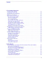
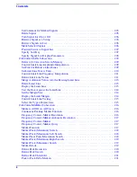
Страница 5: ...48 Overview of GPIB Option A4H 50 GPIB Instrument Nomenclature 50 GPIB Command Statements 50 Overview of RS 232 Option 1AX 52 Settings for the Serial Interface 52 Handshake and Baud Rate 52 Character Format Parameters 52 Modem Line Handshaking 53 Data Transfer Errors 53 Printer Setup and Operation 54 Equipment 54 Interconnection and Setup 54 Testing Printer Operation 56 2 Status Registers Use Stat...

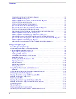
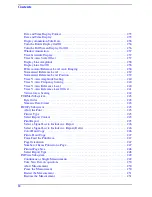
Страница 6: ...e Status Integrity Event Condition and Enable Registers 91 3 Programming Examples List of Programming Examples 94 Programming Examples System Requirements 95 C Programming Examples using VTL 96 Typical Example Program Contents 96 Linking to VTL Libraries 97 Compiling and Linking a VTL Program 97 Example Program 99 Including the VISA Declarations File 99 Opening a Session 100 Device Sessions 100 Ad...

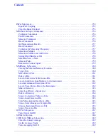
Страница 7: ...Register Query 194 Identification Query 194 Instrument State Query 194 Operation Complete 195 Query Instrument Options 195 Recall 195 Reset 196 Save 196 Service Request Enable 196 Read Status Byte Query 196 Trigger 197 Self Test Query 197 Wait to Continue 197 ABORt Subsystem 198 Abort 198 CALCulate Subsystem 199 NdBpoints 199 NdBresults 199 NdBstate 200 Calculate Correction at Frequency 200 Test C...

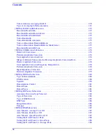
Страница 8: ...mit Line 213 Delete Limit Line 213 Display the Limit Line 213 Test the Data Against the Limit Line 214 Set the Margin Size 214 Display the Limit Margin 214 Control Limit Line Testing 215 Select the Type of Limit Line 215 CALCulate MARKer Subsection 216 Markers All Off on All Traces 216 Continuous Peaking Marker Function 216 Frequency Counter Marker Resolution 216 Frequency Counter Marker Automatic...

Страница 9: ...equency X Position 226 Marker X Axis Readout 226 Span Markers Span X Value 226 Delta Pair Markers Start Frequency X Value 227 Delta Pair Markers Stop Frequency X Value 227 Marker Read Y Value 227 CALCulate NTData Subsection 228 Normalize the Trace Data 228 CALibration Subsystem 229 Align All Instrument Assemblies 229 Set Auto Align Mode All or Not RF 229 Automatic Alignment 230 Return to the Defau...

Страница 10: ...ference Level 240 Trace Y Axis Reference Level Offset 241 Vertical Axis Scaling 242 FORMat Subsystem 243 Byte Order 243 Numeric Data format 243 HCOPy Subsystem 245 Abort the Print 245 Printer Type 245 Select Report Content 245 Print Report 245 Select a Signal List to Include in a Report 246 Select a Signal List to Include in a Report Delta 246 Color Hard Copy 246 Print a Hard Copy 247 Form Feed th...

Страница 11: ... File 260 Move Data to File 261 Delete a File 261 Load a Corrections Table from a File 261 Load a Limit Line from Memory to the Instrument 261 Load an Instrument State from a File 262 Load a Trace From a File to the Instrument 262 Make a Directory 263 Store Load Save a Signal List 263 Delete a Directory 264 Store a Corrections Table to a File 264 Store a Limit Line in a File 265 Store Measurement ...

Страница 12: ...tude Correction Data 277 Delete Amplitude Correction 278 Set Amplitude Correction Frequency Interpolation 278 Perform Amplitude Correction 278 Input Impedance Correction 279 External Amplifier Correction 279 SENSe DEMod Subsection 280 Type of Demodulation 280 FM Deviation 280 Squelch 280 Demodulation Control 281 Demod Time 281 Demod View 281 SENSe DETector Subsection 282 Automatic Detection Type S...

Страница 13: ...Input Port Power Gain 296 Input Port Maximum Mixer Power 296 Optimize Preselector Frequency 296 Preselector Center 297 SENSe SWEep Subsection 298 Sweep Points 298 Set Frequency Domain Scale Type 298 Sweep Time 299 Automatic Sweep Time 299 Sweep Time Mode 300 Time Gating Delay Option 1D6 Only 300 Time Gate Length Option 1D6 Only 300 Time Gate Level Option 1D6 Only 301 Time Gate Polarity Option 1D6 ...

Страница 14: ... 311 Questionable Enable 312 Questionable Event Query 312 Questionable Frequency Condition 312 Questionable Frequency Enable 313 Questionable Frequency Event Query 313 Questionable Frequency Negative Transition 313 Questionable Frequency Positive Transition 314 Questionable Integrity Condition 314 Questionable Integrity Enable 314 Questionable Integrity Event Query 314 Questionable Integrity Negat...

Страница 15: ...rors 323 Host Identification Query 323 License Key Install Application Option 324 Delete a License Key 324 Query Instrument Options 324 Power On Elapsed Time 325 Power On Time 325 Power On Type 325 Enable IF Video Sweep Output Ports 325 Preset 326 Persistent State Reset 326 Preset Type 326 Save User Preset 327 Speaker Control 327 Set Time 327 SCPI Version Query 327 TRACe Subsystem 328 Copy Trace 3...

Страница 16: ...er Line Trigger Delay Value 334 External Trigger Line Trigger Delay Enable 334 External Trigger Slope 334 Trigger Offset 335 Trigger Source 336 Video Trigger Level Amplitude 336 Video Trigger Level Frequency 337 UNIT Subsystem 338 Select Power Units of Measure 338 6 Agilent 8590 EMC Analyzers Programming Conversion Guide ...

Страница 17: ...96 SAV register 196 SRE integer 196 SRE 196 STB 196 TRG 197 TST 197 WAI 197 ABORt 198 CALCulate BWIDth BANDwidth NDB rel_ampl 199 CALCulate BWIDth BANDwidth NDB 199 CALCulate BWIDth BANDwidth RESult 199 CALCulate BWIDth BANDwidth RESult 199 CALCulate BWIDth BANDwidth STATe OFF ON 0 1 200 CALCulate BWIDth BANDwidth STATe 200 CALCulate CLIMits FAIL 200 CALCulate CORRection ATFREquency freq 200 ...

Страница 18: ...s integer 207 CALCulate EMI SLISt SORT FREQ ASC 207 CALCulate EMI SLISt SORT FREQuency PEAK QPEak AVERage LLINE1 LLINE2 ASCending DESending 207 CALCulate EMI SLISt View COMMent PEAK QPEak AVERage 208 CALCulate EMI SLISt View 208 CALCulate LLINe ALL DELete 209 CALCulate LLINe CMODe FIXed RELative 209 CALCulate LLINe CMODe 209 CALCulate LLINe CONTrol DOMain FREQuency TIME 210 CALCulate LLINe CONTrol...

Страница 19: ...Ount RESolution AUTO OFF ON 0 1 217 CALCulate MARKer FCOunt RESolution AUTO 217 CALCulate MARKer FCOunt RESolution 216 CALCulate MARKer MODE SPAN 226 CALCulate MARKer PEAK 220 CALCulate MARKer PEAK EXCursion rel_ampl 220 CALCulate MARKer PEAK EXCursion 220 CALCulate MARKer PEAK SEARch MODE PARameter MAXimum 220 CALCulate MARKer PEAK THReshold ampl 221 CALCulate MARKer PEAK THReshold 221 CALCulate ...

Страница 20: ...2 3 4 TRACe AUTO OFF ON 0 1 223 CALCulate MARKer 1 2 3 4 TRACe AUTO 223 CALCulate MARKer 1 2 3 4 TRACe 223 CALCulate MARKer 1 2 3 4 TRCKing STATe OFF ON 0 1 223 CALCulate MARKer 1 2 3 4 TRCKing STATe 223 CALCulate MARKer 1 2 3 4 X param 224 CALCulate MARKer 1 2 3 4 X CENTer param 224 CALCulate MARKer 1 2 3 4 X CENTer 224 CALCulate MARKer 1 2 3 4 X POSition integer 224 CALCulate MARKer 1 2 3 4 X PO...

Страница 21: ...2 3 4 SET CENTer 221 CALCulate MARKer 1 2 3 4 SET RLEVel 221 CALCulate MARKer 1 2 3 4 SET SPAN 222 CALCulate MARKer 1 2 3 4 SET STARt 222 CALCulate MARKer 1 2 3 4 SET STEP 222 CALCulate MARKer 1 2 3 4 SET STOP 222 CALCulate NTData STATe OFF ON 0 1 228 CALCulate NTData STATe 228 CALibration AUTO OFF ON 0 1 230 CALibration AUTO MODE ALL NRF 229 CALibration AUTO MODE 229 CALibration AUTO 230 CALibrat...

Страница 22: ... EMI PEAKs 259 CONFigure EMI SLISt CURRent MARKed ALL 259 COUPle ALL NONE 233 COUPle 233 DISPlay ANGLe integer 235 DISPlay ANGLe 235 DISPlay ANNotation CLOCk DATE FORMat MDY DMY 235 DISPlay ANNotation CLOCk DATE FORMat 235 DISPlay ANNotation CLOCk STATe OFF ON 0 1 235 DISPlay ANNotation CLOCk STATe 235 DISPlay ANNotation TITLe DATA string 236 DISPlay ANNotation TITLe DATA 236 DISPlay ENABle OFF ON...

Страница 23: ... TRACe Y SCALe PDIVision rel_ampl 240 DISPlay WINDow TRACe Y SCALe PDIVision FREQuency 240 DISPlay WINDow TRACe Y SCALe PDIVision FREQuency 240 DISPlay WINDow TRACe Y SCALe PDIVision 240 DISPlay WINDow TRACe Y SCALe RLEVel ampl 240 DISPlay WINDow TRACe Y SCALe RLEVel OFFSet rel_ampl 241 DISPlay WINDow TRACe Y SCALe RLEVel OFFSet 241 DISPlay WINDow TRACe Y SCALe RLEVel 240 DISPlay WINDow TRACe Y SC...

Страница 24: ... 245 HCOPy IMAGe COLor STATe OFF ON 0 1 246 HCOPy IMAGe COLor STATe 246 HCOPy ITEM FFEed IMMediate 247 HCOPy PAGE ORIentation LANDscape PORTrait 247 HCOPy PAGE ORIentation 247 HCOPy PAGE PRINts integer 247 HCOPy PAGE PRINts 247 HCOPy PAGE SIZE A B A3 A4 LETTer LEGal EXECutive LEDGer 248 HCOPy PAGE SIZE 248 HCOPy REPOrt TYPE SCREen REPort 248 HCOPy IMMediate 247 INITiate ABort 250 INITiate CONTinuo...

Страница 25: ... LIMit LLINE1 LLINE2 file_name 261 MMEMory LOAD SIGNallist file_name 263 MMEMory LOAD STATe 1 file_name 262 MMEMory LOAD TRACe file_name 262 MMEMory MDIRectory dir_path 263 MMEMory RDIRectory dir_name 264 MMEMory STORe CORRection ANTenna CABLe OTHer USER file_name 264 MMEMory STORe LIMit LLINE1 LLINE2 file_name 265 MMEMory STORe RESults file_name 265 MMEMory STORe SCReen file_name 265 MMEMory STOR...

Страница 26: ...ment 306 SOURce POWer SWEep rel_ampl 307 SOURce POWer SWEep 307 SOURce POWer TRCKing integer 307 SOURce POWer TRCKing PEAK 307 SOURce POWer TRCKing 307 SOURce POWer LEVel IMMediate AMPLitude ampl 304 SOURce POWer LEVel IMMediate AMPLitude UP DOWN 304 SOURce POWer LEVel IMMediate AMPLitude 304 STATus OPERation CONDition 308 STATus OPERation ENABle integer 308 STATus OPERation ENABle 308 STATus OPER...

Страница 27: ... STATus QUEStionable FREQuency NTRansition integer 313 STATus QUEStionable FREQuency NTRansition 313 STATus QUEStionable FREQuency PTRansition integer 314 STATus QUEStionable FREQuency PTRansition 314 STATus QUEStionable FREQuency EVENt 313 STATus QUEStionable INTegrity CONDition 314 STATus QUEStionable INTegrity ENABle integer 314 STATus QUEStionable INTegrity ENABle 314 STATus QUEStionable INTeg...

Страница 28: ... 319 SYSTem COMMunicate SERial 1 CONTrol RTS OFF ON IBFull 320 SYSTem COMMunicate SERial 1 CONTrol RTS 320 SYSTem COMMunicate SERial 1 TRANsmit PACE XON NONE 321 SYSTem COMMunicate SERial 1 TRANsmit PACE 321 SYSTem COMMunicate SERial 1 RECeive BAUD baud_rate 320 SYSTem COMMunicate SERial 1 RECeive BAUD 320 SYSTem COMMunicate SERial 1 RECeive PACE XON NONE 321 SYSTem COMMunicate SERial 1 RECeive PA...

Страница 29: ...ESet TYPE FACTory USER MODE 326 SYSTem PRESet USER SAVE 327 SYSTem SPEaker STATe OFF ON 0 1 327 SYSTem SPEaker STATe 327 SYSTem TIME hour minute second 327 SYSTem TIME 327 SYSTem VERSion 327 TRACe COPY source_trace dest_trace 328 TRACe EXCHange trace_1 trace_2 329 TRACe MATH ADD destination_trace source_trace1 source_trace2 329 TRACe MATH MEAN trace 330 TRACe MATH PEAK POINts 330 TRACe MATH PEAK S...

Страница 30: ...TRIGger SEQuence EXTernal 1 SLOPe POSitive NEGative 334 TRIGger SEQuence EXTernal 1 SLOPe 334 TRIGger SEQuence OFFSet 64 bit floating point value 335 TRIGger SEQuence OFFSet 335 TRIGger SEQuence SOURce IMMediate VIDeo LINE EXTernal 336 TRIGger SEQuence SOURce 336 TRIGger SEQuence VIDeo LEVel ampl 336 TRIGger SEQuence VIDeo LEVel FREQuency 337 TRIGger SEQuence VIDeo LEVel FREQuency 337 TRIGger SEQu...

Страница 31: ...ion AUTO OFF ON 0 1 272 SENSe BANDwidth BWIDth RESolution AUTO 272 SENSe BANDwidth BWIDth RESolution MODE EMI SAN OFF 272 SENSe BANDwidth BWIDth RESolution MODE 272 SENSe BANDwidth BWIDth RESolution 272 SENSe CORRection CSET ALL DELete 276 SENSe CORRection CSET ALL STATe OFF ON 0 1 276 SENSe CORRection CSET ALL STATe 276 SENSe CORRection CSET 1 2 3 4 DATA freq rel_ampl freq rel_ampl 276 SENSe CORR...

Страница 32: ...Ction NEGative POSitive SAMPle AVERage RMS 284 SENSe DETector FUNCtion EMI QPEak AVERage OFF 285 SENSe DETector FUNCtion EMI 285 SENSe DETector FUNCtion 284 SENSe DETector FUNCtion EMI VIEW POSitive EMI 286 SENSe DETector FUNCtion EMI VIEW 286 SENSe DETector UNRange 286 SENSe EMI MEASure DETector AVERage DWELl time 288 SENSe EMI MEASure DETector AVERage DWELl 288 SENSe EMI MEASure DETector AVERage...

Страница 33: ...ENSe FREQuency CENTer STEP AUTO OFF ON 0 1 290 SENSe FREQuency CENTer STEP AUTO 290 SENSe FREQuency CENTer STEP INCRement freq 291 SENSe FREQuency CENTer STEP INCRement 291 SENSe FREQuency CENTer 290 SENSe FREQuency SPAN freq 291 SENSe FREQuency SPAN FULL 292 SENSe FREQuency SPAN PREVious 292 SENSe FREQuency SPAN 291 SENSe FREQuency STARt freq 292 SENSe FREQuency STARt 292 SENSe FREQuency STOP fre...

Страница 34: ...LINear LOGarithmic 237 SENSe SWEep SPACing LINear LOGarithmic 298 SENSe SWEep SPACing 298 SENSe SWEep TIME time 299 SENSe SWEep TIME AUTO OFF ON 0 1 299 SENSe SWEep TIME AUTO MODE SRESponse SANalyzer 300 SENSe SWEep TIME AUTO MODE 300 SENSe SWEep TIME AUTO 299 SENSe SWEep TIME GATE DELay time 300 SENSe SWEep TIME GATE DELay 300 SENSe SWEep TIME GATE LENGth time 300 SENSe SWEep TIME GATE LENGth 300...

Страница 35: ...Commands Alphabetical Listing 35 SENSe SWEep TIME GATE STATe OFF ON 0 1 301 SENSe SWEep TIME GATE STATe 301 SENSe SWEep TIME 299 ...

Страница 36: ...36 Commands Alphabetical Listing ...

Страница 37: ...s chapter is to serve as a reminder of SCPI Standard Commands for Programmable Instruments fundamentals to those who have previous experience in programming SCPI This chapter is not intended to teach you everything about the SCPI programming language ...

Страница 38: ...2 IEEE Standard Codes Formats Protocols and Common Commands for Use with ANSI IEEE Std 488 1 1987 New York NY 1992 Valid EMC Analyzer SCPI commands are used for examples in this chapter Topics included in this chapter are Creating Valid Commands Command Notation Syntax Special Characters in Commands Parameters in Commands Improving Measurement Speed Putting Multiple Commands on the Same Line Overv...

Страница 39: ...hey will all cause the same result Sense Band Res 1700 BANDWIDTH RESOLUTION 1 7e3 sens band 1 7KHZ SENS band 1 7E3Hz band 1 7kHz bandwidth RES 1 7e3Hz CALCulate MARKer 1 2 3 4 Y The last command below returns different results than the commands above it The number 3 in the command causes this See the command description for more information CALC MARK Y calc mark y CALC MARK2 Y SENSe DETector FUNCt...

Страница 40: ...strument does not distinguish between upper and lower case letters In the documentation upper case letters indicate the short form of the key word The upper and lower case letters together indicate the long form of the key word Either form may be used in the command Example Trig Seq Vid Lev 2 5V is the same as trigger sequence video level 2 5V NOTE The command TRIGG Sequence Video Level 2 5V is no...

Страница 41: ...are SENSe CHPower BANDwidth INTegration SENSe CHPower BWIDth INTegration Key words in square brackets are optional when composing the command These implied key words will be executed even if they are omitted Command SENSe BANDwidth RESolution AUTO The following commands are all valid and have identical effects bandwidth auto bandwidth resolution auto sense bandwidth auto Angle brackets around a wo...

Страница 42: ... units are sent the indicated default units will be used Units can follow the numerical value with or without a space Variable A variable can be entered in exponential format as well as standard numeric format The appropriate variable range and its optional units are defined in the command description In addition to these values the following key words may also be used in commands where they are a...

Страница 43: ... a positive rational number followed by optional units The default units are dB Acceptable units are dB only string A string parameter includes a series of alpha numeric characters time A time parameter is a rational number followed by optional units The default units are seconds Acceptable units include S MS US Block Program Data Definite length arbitrary block response data is defined in section...

Страница 44: ...ates 12 thousand 3 hundred 20 data bytes follow the header To determine how may points in the block divide 12320 by your selected data format bytes point Divide by 8 for real 64 or 4 for real 32 In this example there are 1540 points in the block if your selected data format is real 64 ...

Страница 45: ...consumes very little instrument resources However in a high throughput application any demand upon instrument resources affects measurement update rate NOTE When auto alignment is off the Align Now All function should be performed periodically Refer to the appropriate Specifications and Characteristics chapter in the Agilent Technologies EMC Analyzers Specifications Guide for more information on h...

Страница 46: ...nnn binary data bytes To parse the data Read two characters D where D tells you how many N characters follow the D character Read D characters the resulting integer specifies the number of data bytes sent Read the bytes into a real array For example suppose the header is 512320 The first character digit in the header 5 tells you how many additional digits there are in the header The 12320 means 12...

Страница 47: ...is the fastest Also check if the loops could be nested in a different order to reduce the number of parameter changes as you step through the test Are you are using the pre configured Measurements MEASURE key Remember that if you have already set your Meas Setup parameters for a measurement and you want to make another one of these measurements later use READ meas The MEASure meas command resets a...

Страница 48: ... case There is no current SCPI standard for RS 232 Although one intent of SCPI is to be interface independent END is only defined for IEEE 488 operation At the time of this writing the RS 232 terminator issue was in the process of being addressed in IEEE standard 1174 A semicolon is not a SCPI terminator it is a separator The purpose of the separator is to queue multiple commands or queries in ord...

Страница 49: ... at the SENSE level You must specify POW to get to the MIX RANG command FREQ STAR 30MHz POW MIX RANG 20dBm FREQ STAR 30MHz POW MIX RANG 20dBm MIX and RANG require a colon to separate them POW ATT 40dB TRIG FREQ STAR 2 3GHz POW ATT 40dB FREQ STAR 2 3GHz FREQ STAR is in the SENSE subsystem not the TRIGGER subsystem POW ATT FREQ STAR POW ATT FREQ STAR POW and FREQ are within the same SENSE subsystem ...

Страница 50: ...y all instruments in the network When combined with the programming language codes they provide all management and data communication instructions for the system Refer to the your programming language manual and your computers I O programming manual for more information The seven fundamental command functions are as follows An abort function that stops all listener talker activity on the interface...

Страница 51: ... does the following 1 Clears the Input Buffer and the Output Queue 2 Resets the parser 3 Clears any current operations such as OPC i e returns the device to Operation Complete Query Idle State and Operation Complete Command Idle State 4 Aborts resumes the current sweep An output function that is used to send function commands and data commands from the controller to the addressed instrument someti...

Страница 52: ...erface Some common serial interface configuration settings are Handshake and Baud Rate To determine hardware operating parameters you need to know the answer for each of the following questions about the peripheral device Which of the following signal and control lines are actively used during communication with the peripheral Data Set Ready DSR Clear to Send CTS What baud rate is expected by the ...

Страница 53: ...ata Terminal Ready signal Data Transfer Errors The serial interface can generate several types of errors when certain conditions are encountered while receiving data from the peripheral device Errors can be generated by any of the following conditions Parity error The parity bit on an incoming character does not match the parity expected by the receiver This condition is most commonly caused by li...

Страница 54: ...nnector using an IEEE 1284 compliant parallel printer cable 3 If appropriate configure your printer using configuration menus or switches Refer to your printer s documentation for more specific information on configuring your printer 4 Turn on the analyzer and printer 5 Press Print Setup on the front panel and then press the Printer Type menu key Printer Type accesses the following keys None None ...

Страница 55: ...r Invalid printer response Define Custom to set up printer This indicates that the analyzer was unable to automatically identify the connected printer and Custom has been selected in the Printer Type menu Press Print Setup Define Custom to select specific printer characteristics such as the printer language PCL3 or PCL5 and color printing capability Once you have set these characteristics to match...

Страница 56: ... Screen and then press Print on the front panel If the printer is ready and the printer setup was successful a printout of the analyzer display will be printed If the printer is not ready the message Printer Timeout will appear on the analyzer display Printer Timeout will remain on the display until the printer is ready or until you press ESC to cancel the printout request ...

Страница 57: ...s This chapter contains a comprehensive description of status registers explaining what status registers are and how to use them Information pertaining to all bits of the registers in Agilent EMC analyzers is also provided ...

Страница 58: ... is comprised of multiple registers arranged in a hierarchical order The service request enable register is at the top of the hierarchy and contains the general status information for the analyzer events and conditions The lower priority status registers propagate their data to the higher priority registers in the data structures by means of summary bits These registers are used to determine the s...

Страница 59: ...egister while reading the following register descriptions Condition Register A condition register continuously monitors the hardware and firmware status of the analyzer There is no latching or buffering for a condition register Negative Transition Filter A negative transition filter specifies the bits in the condition register that will set corresponding bits in the event register when the conditi...

Страница 60: ...60 Chapter 2 Status Registers Use Status Registers to Determine the State of Analyzer Events and Conditions Figure 2 2 Overall Status Register System Diagram ...

Страница 61: ...oduce the request service RQS bit in the status byte register How Do You Access the Status Registers There are two different methods to access the status registers Common Commands Accesses and Controls Status Subsystem Commands Common Command Access and Control Most monitoring of the analyzer conditions is done at the highest level using the following IEEE common commands CLS clear status clears t...

Страница 62: ...atically detect and manage error conditions or changes in analyzer status Either method allows you to monitor one or more conditions The two methods are The Polling Method The Service Request SRQ Method The Polling Method In the polling method the analyzer has a passive role It only tells the controller that conditions have changed when the controller asks the right question The polling method wor...

Страница 63: ...determines how the controller responds to the SRQ Generating a Service Request Before using the SRQ method of generating a service request first become familiar with how service requests are generated Bit 6 of the status byte register is the request service summary RQS bit The RQS bit is set whenever there is a change in the register bit that it has been configured to monitor The RQS bit will rema...

Страница 64: ... use the STATus command to perform the following tasks Check the analyzer hardware and firmware status Do this by querying the condition registers which continuously monitor status These registers represent the current state of the analyzer Bits in a condition register are updated in real time When the condition monitored by a particular bit becomes true the bit is set to 1 When the condition beco...

Страница 65: ... the standard event status register you would send the command ESE 65 1 64 The results of a query are evaluated in a similar way If the STB command returns a decimal value of 140 140 128 8 4 then bit 7 is true bit 3 is true and bit 2 is true Figure 2 3 Status Register Bit Values Details of Bits in All Registers Refer to Figure 2 2 The rest of this chapter lists the bits in each register shown in t...

Страница 66: ...it Decimal Value Description 0 1 Unused This bit is always set to 0 1 2 Unused This bit is always set to 0 2 4 Error Event Queue Summery Bit A 1 in this bit position indicates that the SCPI error queue is not empty The SCPI error queue contains at least one error message 3 8 Questionable Status Summary Bit A 1 in this bit position indicates that the questionable status summary bit has been set The...

Страница 67: ... set to 1 it will trigger a service request Send the SRE 192 128 64 command The SRE command returns the decimal value of the sum of the bits enabled previously with the SRE number command NOTE You must always add 64 the numeric value of RQS bit 6 to your numeric sum when you enable any bits for a service request The service request enable register contains the following bits 5 32 Standard Event St...

Страница 68: ...t status register does not have negative and positive transition registers nor a condition register Use the IEEE common commands at the beginning of Chapter 5 Language Reference in this guide to access the register To query the standard event status register send the ESR command The response will be the decimal sum of the bits which are set to 1 For example if bit number 7 and bit number 3 are set...

Страница 69: ... Operation Complete A 1 in this bit position indicates that all operations were completed following execution of the OPC command 1 2 Request Bus Control This bit is always set to 0 The analyzer does not request control 2 4 Query Error A 1 in this bit position indicates that a query error has occurred Query errors have SCPI error numbers from 499 to 400 3 8 Device Dependent Error A 1 in this bit po...

Страница 70: ...decimal value of the sum of the bits previously enabled with the ESE number command Figure 2 7 Standard Event Status Event Enable Register STATus OPERation Register The STATus OPERation register is used to determine the specific event that sets bit 7 in the status byte register This register also monitors the current measurement state and checks to see if the analyzer is performing any of these fu...

Страница 71: ...Chapter 2 71 Status Registers Use Status Registers to Determine the State of Analyzer Events and Conditions sweeping waiting for a trigger Figure 2 8 Status Operation Register Diagram ...

Страница 72: ...at a measurement is in a wait for trigger state 6 64 Reserved This bit is not used by the analyzer but is for future use with other Agilent products 7 128 Reserved This bit is not used by the analyzer but is for future use with other Agilent products 8 256 Paused A 1 in this bit position indicates that the instrument is in the paused state of the measurement 9 512 Reserved This bit is not used by ...

Страница 73: ...ive read only data Reading data from an event register will clear the content of that register To query the event register send the STATus OPERation EVENt command The STATus OPERation event enable register lets you choose the bits that will set the operation status summary bit bit 7 of the status byte register to 1 Send the STATus OPERation ENABle num command where num is the sum of the decimal va...

Страница 74: ...lter specifies which types of bit state changes in the condition register will set corresponding bits in the event register The changes may be positive from 0 to 1 or negative from 1 to 0 Send the command STATus QUEStionable NTRansition num negative transition or STATus QUEStionable PTRansition num positive transition where num is the sum of the decimal values of the bits you want to enable The Qu...

Страница 75: ... Register Status QUEStionable Negative Transition Filter Status QUEStionable Positive Transition Filter Status 0 1 2 3 4 5 6 7 8 9 10 11 12 14 13 15 0 1 2 3 4 5 6 7 8 9 10 11 12 14 13 15 0 1 2 3 4 5 6 7 8 9 10 11 12 14 13 15 0 1 2 3 4 5 6 7 8 9 10 11 12 14 13 15 0 1 2 3 4 5 6 7 8 9 10 11 12 14 13 15 ck759a FREQuency Summary CALibration Summary INTregrity Sum Reserved Reserved Reserved Reserved Res...

Страница 76: ...76 Chapter 2 Status Registers Use Status Registers to Determine the State of Analyzer Events and Conditions STATus QUEStionable POWer Register Figure 2 10 Questionable Status Power Register Diagram ...

Страница 77: ...output is unleveled 2 4 Source LO Unleveled A 1 in this bit position indicates that the local oscillator LO in the source tracking generator is unleveled 3 8 LO Unleveled A 1 in this bit position indicates that the analyzer local oscillator LO is unleveled 4 16 50 MHz Osc Unleveled A 1 in this bit position indicates that the 50 MHz amplitude reference signal is unleveled 5 32 Reserved This bit is ...

Страница 78: ...le Condition Register are given in the following table Bit Decimal Value Description 0 1 Reserved This bit is not used by the analyzer but are for future use with other Agilent products 1 2 Reserved This bit is not used by the analyzer but are for future use with other Agilent products 2 4 Reserved This bit is not used by the analyzer but are for future use with other Agilent products 3 8 POWer Su...

Страница 79: ...uctive read only Reading data from an event register will clear the content of that register To query the event register send the command STATus QUEStionable POWer EVENt See Questionable Status Event Enable Register on page 77 for an explanation of how to set the summary bit using the event enable register In this case use the command STATus QUEStionable POWer ENABle num 7 128 Reserved This bit is...

Страница 80: ...etermine the State of Analyzer Events and Conditions STATus QUEStionable FREQuency Register Figure 2 12 Questionable Status Frequency Register Diagram Bit descriptions in the Questionable Status Frequency Condition Register are given in the following table ...

Страница 81: ...e analyzer synthesizer is unlocked 5 32 Invalid Span or BW A 1 in this bit position indicates an invalid span or bandwidth during frequency count 6 64 Reserved This bit is not used by the analyzer but are for future use with other Agilent products 7 128 Reserved This bit is not used by the analyzer but are for future use with other Agilent products 8 256 Reserved This bit is not used by the analyz...

Страница 82: ...ister The changes may be positive from 0 to 1 or negative from 1 to 0 Send the command STATus QUEStionable FREQuency NTRansition num negative transition or STATus QUEStionable FREQuency PTRansition num positive transition where num is the sum of the decimal values of the bits you want to enable The Questionable Status Frequency Event register latches transition events from the condition register a...

Страница 83: ...ter 2 83 Status Registers Use Status Registers to Determine the State of Analyzer Events and Conditions STATus QUEStionable CALibration Register Figure 2 13 Questionable Status Calibration Register Diagram ...

Страница 84: ...ing to align the local oscillator LO 6 64 ADC Align Failure A 1 in this bit position indicates that a failure has occurred while trying to align the analog to digital converter ADC 7 128 FM Demod Align Failure A 1 in this bit position indicates that a failure has occurred while trying to align the FM demodulation circuitry 8 256 Misc Sys Align Failure A 1 in this bit position indicates that a fail...

Страница 85: ... Conditions 14 16384 Align Needed A 1 in this bit position indicates that a full alignment is needed perhaps due to a large temperature change having been detected with auto align off or due to default data being used 15 32768 Always Zero 0 This bit is always set to 0 Bit Decimal Value Description ...

Страница 86: ...of Analyzer Events and Conditions STATus QUEStionable INTegrity UNCalibrated Register Figure 2 14 Questionable Status Integrity Uncalibrated Register Diagram Bit descriptions in the Questionable Status Integrity Uncalibrated Condition Register are given in the following table ...

Страница 87: ...librated measurements This is typically caused by sweeping too fast for the current combination of span resolution bandwidth and video bandwidth Auto coupling may resolve this problem 1 2 Signal Ident ON A 1 in this bit position indicates that amplitude measurements may be in error due to signal identification routines being active Amplitude accuracy is degraded when signal identification is activ...

Страница 88: ...s of the analyzer Condition registers are read only To query the condition register send the command STATus QUEStionable INTegrity UNCalibrated CONDition The response will be the decimal sum of the bits which are set to 1 The transition filter specifies which types of bit state changes in the condition register will set corresponding bits in the event register The changes may be positive from 0 to...

Страница 89: ...etermine the State of Analyzer Events and Conditions STATus QUEStionable INTegrity Register Figure 2 15 Questionable Status Integrity Register Diagram Bit descriptions in the Questionable Status Integrity Condition Register are given in the following table ...

Страница 90: ...nt products 6 64 Reserved This bit is not used by the analyzer but are for future use with other Agilent products 7 128 Reserved This bit is not used by the analyzer but are for future use with other Agilent products 8 256 Reserved This bit is not used by the analyzer but are for future use with other Agilent products 9 512 Reserved This bit is not used by the analyzer but are for future use with ...

Страница 91: ...ges may be positive from 0 to 1 or negative from 1 to 0 Send the command STATus QUEStionable INTegrity NTRansition num negative transition or STATus QUEStionable INTegrity PTRansition num positive transition where num is the sum of the decimal values of the bits you want to enable The Questionable Status Integrity Event Register latches transition events from the condition register as specified by...

Страница 92: ...92 Chapter 2 Status Registers Use Status Registers to Determine the State of Analyzer Events and Conditions ...

Страница 93: ...des examples of how to program the analyzer using the analyzer SCPI programming commands Twelve examples are written for an analyzer with an GPIB interface Option A4H Three examples are written for an analyzer with an RS 232 interface Option 1AX ...

Страница 94: ...ment Reading Trace Data using ASCII Format GPIB Reading Trace Data Using 32 bit Real Format GPIB Reading Trace Data Using ASCII Format RS 232 Reading Trace Data Using 32 bit Real Format RS 232 Using Limit Lines Measuring Noise Entering Amplitude Correction Data Status Register Determine When a Measurement is Done Determine if an Error has Occurred Measuring Harmonic Distortion GPIB Measuring Harmo...

Страница 95: ...OM1 serial port configured as follows for analyzers with Option 1AX 9600 baud 8 data bits 1 stop bit no parity bits hardware flow control A HP Agilent 82341C card may be substituted for the National Instruments GPIB and the HP VISA libraries may be substituted for the National Instruments VISA Transition Libraries If substitutions are made the subdirectories for the include and library files will ...

Страница 96: ...o VTL Libraries on page 97 Compiling and Linking a VTL Program on page 97 Example Program on page 99 Including the VISA Declarations File on page 99 Opening a Session on page 100 Device Sessions on page 100 Addressing a Session on page 102 Closing a Session on page 103 Typical Example Program Contents The following is a summary of the VTL function calls used in the example programs visa h This fil...

Страница 97: ...t libraries 32 bit Version assumes Windows 95 operating system C VXIPNP WIN95 LIB MSC VISA32 LIB for Microsoft compilers C VXIPNP WIN95 LIB BC VISA32 LIB for Borland compilers 16 bit Version C VXIPNP WIN LIB MSC VISA LIB for Microsoft compilers C VXIPNP WIN LIB BC VISA LIB for Borland compilers See the following section for information on how to use the VTL run time libraries Compiling and Linking...

Страница 98: ...B MSC For Borland C version 4 0 compilers You may wish to add the include file and library file search paths They are set under the Options Project menu selection Double click on Directories from the Topics list box and add the following C VXIPNP WIN95 INCLUDE C VXIPNP WIN95 LIB BC 16 bit Applications The following is a summary of important compiler specific considerations for the Windows compiler...

Страница 99: ... defaultRM GPIB0 18 INSTR VI_NULL VI_NULL vi Initialize device viPrintf vi RST n Send an IDN string to the device printf vi IDN n Read results viScanf vi t buf Print results printf Instrument identification string s n buf Close the sessions viClose vi viClose defaultRM Including the VISA Declarations File For C and C programs you must include the visa h header file at the beginning of every file t...

Страница 100: ...e across interfaces Typically a device is an instrument but could be a computer a plotter or a printer NOTE All devices that you will be using need to be connected and in working condition prior to the first VTL function call viOpenDefaultRM The system is configured only on the first viOpenDefaultRM per process Therefore if viOpenDefaultRM is called without devices connected and then called again ...

Страница 101: ...revious function calls sesn This is a session returned from the viOpenDefaultRM function that identifies the resource manager session rsrcName This is a unique symbolic name of the device device address accessMode This parameter is not used for VTL Use VI_NULL timeout This parameter is not used for VTL Use VI_NULL vi This is a pointer to the session identifier for this particular device session Th...

Страница 102: ...guration Utility This name is usually the interface type followed by a number The following table illustrates the format of the rsrcName for the different interface types The following describes the parameters used above board This optional parameter is used if you have more than one interface of the same type The default value for board is 0 VXI logical address This is the logical address of the ...

Страница 103: ...ess 23 ViSession defaultRM vi viOpenDefaultRM defaultRM viOpen defaultRM GPIB0 23 INSTR VI_NULL VI_NULL vi viClose vi viClose defaultRM Closing a Session The viClose function must be used to close each session You can close the specific device session which will free all data structures that had been allocated for the session If you close the default resource manager session all sessions opened us...

Страница 104: ... Resets the Analyzer RST Sets the analyzer center frequency span and units SENS FREQ CENT freq SENS FREQ SPAN freq UNIT POW DBM Set the input port to the 50 MHz amplitude reference CAL SOUR STAT ON Set the analyzer to single sweep mode INIT CONT 0 Prompt the user for peak excursion and set them CALC MARK PEAK EXC dB Set the peak threshold to 90 dBm TRAC MATH PEAK THR STAT ON TRAC MATH PEAK THR 90 ...

Страница 105: ...d Route50MHzSignal viQueryf viESA IDN n t cIdBuff iResult strncmp cIdBuff hpESA_IDN_E4401B strlen hpESA_IDN_E4401B strncmp cIdBuff hpESA_IDN_E4411B strlen hpESA_IDN_E4411B strncmp cIdBuff hpEMC_IDN_E7401A strlen hpEMC_IDN_E7401A if iResult 0 Set the input port to the 50MHz amplitude reference for the models E4401B E4411B and E7401A viPrintf viESA CAL SOUR STAT ON n else For the analyzers having fr...

Страница 106: ...A Reset the instrument viPrintf viESA RST n Set Y Axis units to dBm viPrintf viESA UNIT POW DBM n Set the analyzer center frequency to 50MHZ viPrintf viESA SENS FREQ CENT 50e6 n Set the analyzer span to 50MHZ viPrintf viESA SENS FREQ SPAN 50e6 n Display the program heading printf n t t Marker Program n n Check for the instrument model number and route the 50MHz signal accordingly Route50MHzSignal ...

Страница 107: ...WAI n Set the marker to the maximum peak viPrintf viESA CALC MARK MAX n Query and read the marker frequency viQueryf viESA CALC MARK X n lf dMarkerFreq printf n t RESULT Marker Frequency is lf MHZ n n dMarkerFreq 10e5 Query and read the marker amplitude viQueryf viESA CALC MARK Y n lf dMarkerAmpl printf t RESULT Marker Amplitude is lf dBm n n dMarkerAmpl Close the session viClose viESA viClose def...

Страница 108: ...t port to the 50 MHz amplitude reference CAL SOUR STAT ON Set the analyzer to single sweep mode INIT CONT 0 Prompts the user for the start and stop frequencies Sets the start and stop frequencies SENS FREQ START freq SENS FREQ STOP freq Trigger a sweep and wait for sweep completion INIT IMM WAI Set the marker to the maximum peak CALC MARK MAX Set the analyzer to activate the delta marker CALC MARK...

Страница 109: ...strncmp cIdBuff hpESA_IDN_E4401B strlen hpESA_IDN_E4401B strncmp cIdBuff hpESA_IDN_E4411B strlen hpESA_IDN_E4411B strncmp cIdBuff hpEMC_IDN_E7401A strlen hpEMC_IDN_E7401A if iResult 0 Set the input port to the 50MHz amplitude reference for the models E4401B E4411B and E7401A viPrintf viESA CAL SOUR STAT ON n else For the analyzers having frequency limits 3GHz prompt the user to connect the amplitu...

Страница 110: ...m n n Check for the instrument model number and route the 50MHz signal accordingly Route50MHzSignal Set the analyzer to single sweep mode viPrintf viESA INIT CONT 0 n Prompt the user for the start frequency printf t Enter the Start frequency in MHz The user enters the start frequency scanf lf dStartFreq Prompt the user for the stop frequency printf t Enter the Stop frequency in MHz The user enters...

Страница 111: ...C MARK MODE DELT n Trigger a sweep wait for completion viPrintf viESA INIT IMM WAI n Set the marker to minimum amplitude viPrintf viESA CALC MARK MIN n Query and read the marker amplitude viQueryf viESA CALC MARK Y n lf dMarkerAmplitude print the marker amplitude printf n n tRESULT Marker Amplitude Delta lf dB n n dMarkerAmplitude Close the session viClose viESA viClose defaultRM ...

Страница 112: ...not only determine when the alignment has been completed but the pass fail status of the align ment process This C programming example does the following The SCPI instrument commands used are given as reference Opens a GPIB session at address 18 Clears the Analyzer CLS Resets the Analyzer RST VISA function sets the time out to infinite Initiate self alignment CAL ALL Query for operation complete O...

Страница 113: ...strncmp cIdBuff hpEMC_IDN_E7401A strlen hpEMC_IDN_E7401A if iResult 0 Set the input port to the 50MHz amplitude reference for the models E4401B E4411B and E7401A viPrintf viESA CAL SOUR STAT ON n else For the analyzers having frequency limits 3GHz prompt the user to connect the amplitude reference output to the input printf Connect AMPTD REF OUT to the INPUT n printf Press Return to continue n sca...

Страница 114: ...viSetAttribute viESA VI_ATTR_TMO_VALUE VI_TMO_INFINITE printf t Performing first self alignment Initiate a self alignment viPrintf viESA CAL ALL n Query for operation complete viQueryf viESA OPC n d lOpc printf n n t First Self Alignment is Done n n if lOpc printf Program Abort error ocurred last command was not completed n exit 0 printf n n t Press Return to continue with next alignment n n scanf...

Страница 115: ...Chapter 3 115 Programming Examples Performing Internal Self alignment printf Program Abort error ocurred last command was not completed n exit 0 Close the session viClose viESA viClose defaultRM ...

Страница 116: ...402 E4403B E4404BE 4405B E4407B or E4408B Prompt to connect AMPTD REF OUT to INPUT CAL SOUR STAT ON Query for the number of sweep points only applies to firmware revisions A 04 00 and later default is 401 SENS SWE POIN Sets the analyzer center frequency to 50 MHz SENS FREQ CENT 50 MHZ Sets the analyzer span to 50 MHz SENS FREQ SPAN 50 MHZ Set the analyzer to single sweep mode INIT CONT 0 Trigger a...

Страница 117: ...reference void Route50MHzSignal viQueryf viESA IDN n t cIdBuff iResult strncmp cIdBuff hpESA_IDN_E4401B strlen hpESA_IDN_E4401B strncmp cIdBuff hpESA_IDN_E4411B strlen hpESA_IDN_E4411B strncmp cIdBuff hpEMC_IDN_E7401A strlen hpEMC_IDN_E7401A if iResult 0 Set the input port to the 50MHz amplitude reference for the models E4401B E4411B and E7401A viPrintf viESA CAL SOUR STAT ON n else For the analyz...

Страница 118: ... viESA if viStatus printf Could not open a session to GPIB device at address 18 n exit 0 Clear the instrument viClear viESA Reset the instrument This will set number of sweep points to default of 401 viPrintf viESA RST n Display the program heading printf n t t Read in Trace Data using ASCII Format GPIB Program n n Check for the instrument model number and route the 50MHz signal accordingly Route5...

Страница 119: ...e Trace Data using ASCII Format viQueryf viESA s n t TRAC DATA TRACE1 iNum cResult Remove the from the ASCII trace data for analyzing data cToken strtok cResult Save trace data to an ASCII to a file by removing the token fTraceFile fopen C temp ReadAscGpib txt w fprintf fTraceFile ReadAscGpib exe Output nAgilent Technologies 2000 n n fprintf fTraceFile tAmplitude of point d s dBm n lCount 1 cToken...

Страница 120: ...r of sweep points for firmware revisions A 04 00 and later Default is 401 SENS SWE POIN Calculate the number of bytes in the header Set the analyzer to single sweep mode INIT CONT 0 Sets the analyzer center frequency and span to 50 MHz SENS FREQ CENT 50 MHZ SENS FREQ SPAN 50 MHZ Specify 10 dB per division for the amplitude scale in and dBm Units DISP WIND TRAC Y SCAL PDIV 10 dB UNIT POW DBM Set th...

Страница 121: ...f viESA IDN n t cIdBuff iResult strncmp cIdBuff hpESA_IDN_E4401B strlen hpESA_IDN_E4401B strncmp cIdBuff hpESA_IDN_E4411B strlen hpESA_IDN_E4411B strncmp cIdBuff hpEMC_IDN_E7401A strlen hpEMC_IDN_E7401A if iResult 0 Set the input port to the 50MHz internal reference source for the models E4401B E4411B and E7401A viPrintf viESA CAL SOUR STAT ON n else For the analyzers having frequency limits 3GHz ...

Страница 122: ...at address 18 n exit 0 Clear the instrument viClear viESA Reset the instrument This will set number of sweep points to default of 401 viPrintf viESA RST n Display the program heading printf n t t Read in Trace Data using 32 bit Real Format using GPIB n n Set the input port to the 50MHz amplitude reference Route50MHzSignal Query number of sweep points per trace firmware revision A 04 00 and later F...

Страница 123: ...Printf viESA FORM DATA REAL 32 n Set the binary byte order to SWAP viPrintf viESA FORM BORD SWAP n Trigger a sweep and wait for sweep to complete viPrintf viESA INIT IMM WAI n Calculate size of trace record This will be sum of HeaderBytes NumberBytes the actual data bytes and the n terminator iSize lNumberBytes iHeaderBytes 1 Get trace header data and trace data viPrintf viESA TRAC DATA TRACE1 n v...

Страница 124: ...er3 Programming Examples Reading Trace Data Using 32 bit Real Format GPIB fprintf fTraceFile tAmplitude of point d 2lf dBm n i 1 dTraceArray i fclose fTraceFile Close the session viClose viESA viClose defaultRM ...

Страница 125: ...the input port to the 50 MHz amplitude reference CAL SOUR STAT ON Query for the number of sweep points for firmware revisions A 04 00 and later Default is 401 SENS SWE POIN Set the analyzer to single sweep mode INIT CONT 0 Sets the analyzer center frequency and span to 50 MHz SENS FREQ CENT 50 MHZ SENS FREQ SPAN 50 MHZ Trigger a sweep INIT IMM Check for operation complete OPC Specify dBm Unit UNIT...

Страница 126: ...eference void Route50MHzSignal viQueryf viESA IDN n t cIdBuff iResult strncmp cIdBuff hpESA_IDN_E4401B strlen hpESA_IDN_E4401B strncmp cIdBuff hpESA_IDN_E4411B strlen hpESA_IDN_E4411B strncmp cIdBuff hpEMC_IDN_E7401A strlen hpEMC_IDN_E7401A if iResult 0 Set the input port to the 50MHz amplitude reference for the models E4411B and E4401B viPrintf viESA CAL SOUR STAT ON n else For the analyzers havi...

Страница 127: ...printf Could not open a session to ASRL device at COM1 n exit 0 Clear the instrument viClear viESA Reset the instrument This will set number of sweep points to default of 401 viPrintf viESA RST n Display the program heading printf n t tRead in Trace Data using ASCII Format RS232 Program n n Check for the instrument model number and route the 50MHz signal accordingly Route50MHzSignal Query number o...

Страница 128: ...m measurement viPrintf viESA INIT IMM n Read the operation complete query viQueryf viESA OPC n d lOpc if lOpc printf Program Abort error ocurred last command was not completed n exit 0 Query the Trace Data using ASCII Format viQueryf viESA s n t TRAC DATA TRACE1 iNum cResult Remove the from the ASCII trace data for analyzing data cToken strtok cResult Save trace data to an ASCII to a file by remov...

Страница 129: ...g Examples Reading Trace Data Using ASCII Format RS 232 dBm n lCount 1 cToken fprintf fTraceFile nThe Total trace data points of the spectrum are d n n lCount fclose fTraceFile Close the session viClose viESA viClose defaultRM ...

Страница 130: ...or firmware revision A 04 00 and later Default is 401 SENS SWE POIN Calculate the number of bytes in the header Set the analyzer to single sweep mode INIT CONT 0 Sets the analyzer center frequency and span to 50 MHz SENS FREQ CENT 50 MHZ SENS FREQ SPAN 50 MHZ Specify 10 dB per division for the amplitude scale in and dBm Units DISP WIND TRAC Y SCAL PDIV 10 dB UNIT POW DBM Set the analyzer trace dat...

Страница 131: ...sion defaultRM viESA ViStatus errStatus ViChar cIdBuff 256 0 char cEnter 0 int iResult 0 Set the input port to 50MHz amplitude reference void Route50MHzSignal viQueryf viESA IDN n t cIdBuff iResult strncmp cIdBuff hpESA_IDN_E4401B strlen hpESA_IDN_E4401B strncmp cIdBuff hpESA_IDN_E4411B strlen hpESA_IDN_E4411B strncmp cIdBuff hpEMC_IDN_E7401A strlen hpEMC_IDN_E7401A if iResult 0 Set the input port...

Страница 132: ...f points per sweep int iDataBytes 1604 Number of data points assuming 4 bytes per point int iHeaderBytes 6 Number of bytes in the header assuming 1604 data bytes FILE fTraceFile Open a serial session at COM1 viStatus viOpenDefaultRM defaultRM if viStatus viOpen defaultRM ASRL1 INSTR VI_NULL VI_NULL viESA VI_SUCCESS printf Could not open a session to ASRL device at COM1 n exit 0 Clear the instrumen...

Страница 133: ...n iDataBytes iSwpPnts iBytesPerPnt lNumberBytes iDataBytes while iDataBytes iDataBytes 10 0 iHeaderBytes Set analyzer to single sweep mode viPrintf viESA INIT CONT 0 n Set the analyzer to 50MHz center frequency viPrintf viESA SENS FREQ CENT 50 MHZ n Set the analyzer to 50MHz Span viPrintf viESA SENS FREQ SPAN 50 MHZ n Specify dB per division of each vertical division Units viPrintf viESA DISP WIND...

Страница 134: ... and trace data viPrintf viESA TRAC DATA TRACE1 n viRead viESA ViBuf cResult iSize lRetCount Reset timeout to 3 sec viSetAttribute viESA VI_ATTR_TMO_VALUE 3000 Extract the trace data memcpy dTraceArray cResult iHeaderBytes size_t lNumberBytes Save trace data to an ASCII file fTraceFile fopen C temp ReadTrace32Rs232 txt w fprintf fTraceFile ReadTrace32Rs232 exe Output nHewlett Packard 1999 n n fpri...

Страница 135: ...ONT DOM FREQ CALC LLINE1 TYPE UPP CALC LLINE1 DISP ON CALC LLINE1 DATA freq1 amp1 1 freq2 amp2 1 Define the lower limit line to have frequency amplitude pairs CALC LLINE2 CONT DOM FREQ CALC LLINE2 TYPE LOW CALC LLINE2 DISP ON CALC LLINE2 DATA freq1 amp1 1 freq2 amp2 1 Turn the limit line test function on CALC LLINE2 STAT ON Set the analyzer to a center frequency of 50 MHz span to 20 MHz and resolu...

Страница 136: ...ckard E4401B define hpESA_IDN_E4411B Hewlett Packard E4411B define hpEMC_IDN_E7401A Hewlett Packard E7401A ViSession defaultRM viESA ViStatus errStatus ViChar cIdBuff 256 0 char cEnter 0 int iResult 0 long lLimitTest 0L Set the input port to 50MHz amplitude reference void Route50MHzSignal viQueryf viESA IDN n t cIdBuff iResult strncmp cIdBuff hpESA_IDN_E4401B strlen hpESA_IDN_E4401B strncmp cIdBuf...

Страница 137: ...Test 0 printf n t Limit Line Failed n viQueryf viESA CALC LLINE1 FAIL n ld lLimitTest if lLimitTest 0 printf n t Limit Line1 Passed n else printf n t Limit Line1 Failed n viQueryf viESA CALC LLINE2 FAIL n ld lLimitTest if lLimitTest 0 printf n t Limit Line2 Passed n else printf n t Limit Line2 Failed n else printf n t Limit Test Pass n void main Program Variable ViStatus viStatus 0 long lOpc 0L Op...

Страница 138: ...wing frequency amplitude pairs viPrintf viESA CALC LLINE1 TYPE UPP n Turn on display viPrintf viESA CALC LLINE1 DISP ON n Send the upper limit line data viPrintf viESA CALC LLINE1 DATA 40E06 50 1 45E06 20 1 50E06 15 1 55E06 20 1 60E06 50 1 n Turn on display viPrintf viESA CALC LLINE1 DISP ON n Delete any current limit line and define the lower limit line to have the following frequency amplitude p...

Страница 139: ...Check for operation complete viQueryf viESA OPC n d lOpc if lOpc printf Program Abort error ocurred last command was not completed n exit 0 Check to see if limit line passes or fails It should pass printf n t Limit Line status after activating the 50MHz signal n Print the limits line result printResult Pause for 5 seconds YIELD Deactivate the 50 MHz alignment signal viPrintf viESA CAL SOUR STAT OF...

Страница 140: ...140 Chapter3 Programming Examples Using Limit Lines Print the limits line result printResult Close the session viClose viESA viClose defaultRM ...

Страница 141: ...e input port to the 50 MHz amplitude reference CAL SOUR STAT ON Set the analyzer to single sweep mode INIT CONT 0 Trigger a sweep and wait for sweep completion INIT IMM WAI Set the marker to the maximum peak CALC MARK MAX Set the analyzer to active delta marker CALC MARK MODE DELT Set the delta marker to 2 MHZ CALC MARK X 2E 6 Activate the noise marker function CALC MARK FUNC NOIS Trigger a sweep ...

Страница 142: ...al viQueryf viESA IDN n t cIdBuff iResult strncmp cIdBuff hpESA_IDN_E4401B strlen hpESA_IDN_E4401B strncmp cIdBuff hpESA_IDN_E4411B strlen hpESA_IDN_E4411B strncmp cIdBuff hpEMC_IDN_E7401A strlen hpEMC_IDN_E7401A if iResult 0 Set the input port to the 50MHz amplitude reference for the models E4401B E4411B amd E7401A viPrintf viESA CAL SOUR STAT ON n else For the analyzers having frequency limits 3...

Страница 143: ...eading printf n t t Noise Program n n Check for the instrument model number and route the 50MHz signal accordingly Route50MHzSignal Set the analyzer center frequency to 50MHz viPrintf viESA SENS FREQ CENT 50e6 n Set the analyzer span to 10MHz viPrintf viESA SENS FREQ SPAN 10e6 n Set the analyzer in a single sweep mode viPrintf viESA INIT CONT 0 n Trigger a sweep and wait for sweep completion viPri...

Страница 144: ... active marker two divisions to the right of the input signal viPrintf viESA CALC MARK X 2E 6 n Activate the noise marker function viPrintf viESA CALC MARK FUNC NOIS n Trigger a sweep and wait for sweep completion viPrintf viESA INIT IMM WAI n Query and read the marker delta amplitude from the analyzer viQueryf viESA CALC MARK Y n lf dMarkAmp Report the marker delta amplitude as the carrier to noi...

Страница 145: ...ut port to the 50 MHz amplitude reference CAL SOUR STAT ON Enter amplitude correction frequency amplitude pairs 0 Hz 0 dB 100 MHz 5 dB 1 GHz 5 dB 1 5 GHz 10 dB SENS CORR CSET1 DATA 0 0 100E6 5 0 1 0E9 5 0 Activate amplitude correction SENS CORR CSET1 DATA SENS CORR CSET1 ALL STAT ON Query the analyzer for the amplitude corection factors SENS CORR CSET1 DATA Store them in an array Display the array...

Страница 146: ..._E7401A if iResult 0 Set the input port to the 50MHz amplitude reference for the models E4401B E4411B and E7401A viPrintf viESA CAL SOUR STAT ON n else For the analyzers having frequency limits 3GHz prompt the user to connect the amplitude reference output to the input printf Connect AMPTD REF OUT to the INPUT n printf Press Return to continue n scanf c cEnter Externally route the 50MHz Signal viP...

Страница 147: ... Check for the instrument model number and route the 50MHz signal accordingly Route50MHzSignal Purge any currently loaded amplitude correction factors viPrintf viESA SENS CORR CSET1 DEL n Enter amp cor frequency amplitude pairs 0 Hz 0 dB 100 MHz 5 dB 1 GHz 5 dB 1 5GHz 10 viPrintf viESA SENS CORR CSET1 DATA viPrintf viESA 0 0 0 viPrintf viESA 100 E6 5 0 viPrintf viESA 1 E9 5 0 viPrintf viESA 1 5E9 ...

Страница 148: ...pltd 1 lCount atof cToken while cToken NULL lCount if lCount iNoOfPoints lCount break Remove the from the amplitude correction for analyzing data cToken strtok NULL Store the array frequency value into a two dimensional real array aRealArray lFreq lCount atof cToken cToken strtok NULL Store the array amplitude value into a two dimensional real array aRealArray lAmpltd lCount atof cToken Display th...

Страница 149: ... 0 Route the amplitude reference to the analyzer input CAL SOUR STAT ON Set the analyzer center frequency span and Res BW SENS FREQ CENT 50 MHz SENS FREQ SPAN 10 MHz SENS BAND RES 300 kHz Trigger a sweep and wait for completion of sweep INIT IMM OPC Sets the service request mask to assert SRQ when either a measurement is uncalibrated or an error message has occurred SRE 96 ESE 35 Set the computer ...

Страница 150: ...lib h include math h include conio h include ctype h include string h include windows h include visa h define hpESA_IDN_E4401B Hewlett Packard E4401B define hpESA_IDN_E4411B Hewlett Packard E4411B define hpEMC_IDN_E7401A Hewlett Packard E7401A define YIELD Sleep 10 ViSession defaultRM viESA ViStatus errStatus ViChar cIdBuff 256 0 ViAddr iAddress char cEnter 0 int iResult 0 int iSrqOccurred 0 char ...

Страница 151: ...n hpESA_IDN_E4411B strncmp cIdBuff hpEMC_IDN_E7401A strlen hpEMC_IDN_E7401A if iResult 0 Set the input port to the 50MHz amplitude reference for the models E4401B E4411B and E7401A viPrintf viESA CAL SOUR STAT ON n else For the analyzers having frequency limits 3GHz prompt the user to connect the amplitude reference output to the input printf Connect AMPTD REF OUT to the INPUT n printf Press Retur...

Страница 152: ... has interrupted viQueryf viESA SYST COMM GPIB SELF ADDR n t cBuf printf n Instrument at GPIB address s has generated an interrupt n cBuf Get the status byte If the ESA generated the interrupt determine the nature of the interrupt did the measurement complete or an error message occur viQueryf viESA ESR n d iStatusByte if 0x01 iStatusByte printf n SRQ message t Measurement complete n else if 0x02 ...

Страница 153: ...te the 50MHz signal accordingly Route50MHzSignal Set the analyzer to 50MHz center frequency viPrintf viESA SENS FREQ CENT 50 MHz n Set the analyzer resolution bandwidth to 300 Khz viPrintf viESA SENS BAND RES 300 KHz n Set the analyzer to 10MHz span viPrintf viESA SENS FREQ SPAN 10MHz n Trigger a sweep viPrintf viESA INIT IMM n Make sure the previous command has been completed viQueryf viESA OPC n...

Страница 154: ...iPrintf viESA SENS AVER TYPE LPOW SENS AVER COUN 80 SENS AVER STAT ON n Set the service request mask to assert SRQ when either a measurement is completed or an error message has occurred viPrintf viESA SRE 96 n viPrintf viESA ESE 35 n Trigger the sweeps and set the OPC bit after the sweeps are completed viPrintf viESA INIT IMM OPC n Wait for SRQ WaitForSRQ Disable and uninstall the interrupt handl...

Страница 155: ...age has occurred STAT QUES ENAB 512 STAT QUES INT ENAB 8 ESE 35 SRE 104 Set the center frequency to 500MHz and span to 100MHz SENS FREQ CENT 500 MHZ SENS FREQ SPAN 100 MHZ Set the analyzer to an uncalibrated state When an interrupt occurs poll all instruments Report the nature of the interrupt on the ESA analyzer Pause 5 seconds to observe the analyzer Sets the service request mask to assert SRQ w...

Страница 156: ...Packard E4411B define hpEMC_IDN_E7401A Hewlett Packard E7401A define YIELD Sleep 10 ViSession defaultRM viESA ViStatus errStatus ViChar cIdBuff 256 0 char cEnter 0 int iResult 0 int iSrqOccurred 0 char cBuf 3 0 Wait until SRQ is generated and for the handler to be called Print something while waiting When interrupt occurs it will be handled by interrupt handler void WaitForSRQ long lCount 0L iSrqO...

Страница 157: ...7401A viPrintf viESA CAL SOUR STAT ON n else For the analyzers having frequency limits 3GHz prompt the user to connect the amplitude reference output to the input printf Connect AMPTD REF OUT to the INPUT n printf Press Return to continue n scanf c cEnter Externally route the 50MHz Signal viPrintf viESA CAL SOUR STAT ON n Interrupt handler trigger event handler ViStatus _VI_FUNCH sSrqHdlr ViSessio...

Страница 158: ...rror message has occurred viQueryf viESA STAT QUES INT EVEN n d iStatusByte if 0x08 iStatusByte printf n SRQ message t Measurement uncalibrated n If the ESA generated the interrupt determine the nature of the interrupt did is the measurement complete or an error message occur viQueryf viESA ESR n d iStatusByte if iStatusByte 0 0x01 iStatusByte printf n SRQ message t Measurement complete n else if ...

Страница 159: ...Uncal displayed on screen or an error message has occurred viPrintf viESA STAT QUES ENAB 512 n viPrintf viESA STAT QUES INT ENAB 8 n viPrintf viESA ESE 35 n viPrintf viESA SRE 104 n Configure the computer to respond to an interrupt install the handler and enable it viInstallHandler viESA VI_EVENT_SERVICE_REQ sSrqHdlr ViAddr 10 viEnableEvent viESA VI_EVENT_SERVICE_REQ VI_HNDLR VI_NULL iSrqOccurred ...

Страница 160: ...k to assert SRQ when either a measurement is completed or an error message has occurred viPrintf viESA SRE 96 n viPrintf viESA ESE 35 n Send an undefined command to the device viPrintf viESA IDN n Wait for SRQ WaitForSRQ Disable and uninstall the interrupt handler viDisableEvent viESA VI_EVENT_SERVICE_REQ VI_HNDLR viUninstallHandler viESA VI_EVENT_SERVICE_REQ sSrqHdlr ViAddr 10 Clear the instrumen...

Страница 161: ...ce CAL SOUR STAT ON Set the analyzer center frequency to the fundamental SENS FREQ CENT freq Set the analyzer to 10 MHz span SENS FREQ SPAN 10 MHZ Set the analyzer to single sweep mode INIT CONT 0 Take a sweep and wait for sweep completion INIT IMM WAI Perform the peak search CALC MARK MAX Set the marker to reference level CALC MARK SET RLEV Take a sweep and wait for sweep completion INIT IMM WAI ...

Страница 162: ...tal amplitude in volts CALC MARK Y Read the marker frequency CALC MARK X Measure each harmonic amplitude as follows Set the span to 20 MHz SENS FREQ SPAN 20 MHZ Set the center frequency to the desired harmonic SENS FREQ CENT freq Take a sweep and wait for operation complete INIT IMM OPC Perform peak search CALC MARK MAX Set VISA timeout to 60 seconds Activate signal track CALC MARK TRCK STAT ON Zo...

Страница 163: ...th h include conio h include ctype h include string h include visa h define hpESA_IDN_E4401B Hewlett Packard E4401B define hpESA_IDN_E4411B Hewlett Packard E4411B definehpEMC_IDN_E7401A Hewlett Packard E7401A ViSession defaultRM viESA ViStatus errStatus ViChar cIdBuff 256 0 char cEnter 0 int iResult 0 long lOpc 0L Set the input port to 50MHz amplitude reference void Route50MHzSignal viQueryf viESA...

Страница 164: ...akeSweep Take a sweep and wait for the sweep completion viPrintf viESA INIT IMM n viQueryf viESA OPC n d lOpc if lOpc printf Program Abort Error occurred last command was not completed n exit 0 void main Program Variables ViStatus viStatus 0 double dFundamental 0 0 double dHarmFreq 0 0 float fHarmV 10 0 0 float fHarmDbm 10 0 0 float fRelAmptd 10 0 0 float fFundaAmptdDbm 0 0 double dFundaAmptdV 0 0...

Страница 165: ...Signal Prompt user for fundamental frequency printf t Enter the input signal fundamental frequency in MHz The user enters fundamental frequency scanf lf dFundamental Set the analyzer center frequency to the fundamental frequency viPrintf viESA SENS FREQ CENT lf MHZ n dFundamental Set the analyzer to 10MHz Span viPrintf viESA SENS FREQ SPAN 10 MHZ n Put the analyzer in a single sweep viPrintf viESA...

Страница 166: ...weep De activate the signal track viPrintf viESA CALC MARK TRCK STAT OFF n Reset timeout to 3 sec viSetAttribute viESA VI_ATTR_TMO_VALUE 3000 Set units to DBM viPrintf viESA UNIT POW DBM n Perform a peak search viPrintf viESA CALC MARK MAX n Read the marker amplitude this is the fundamental amplitude in dBm viQueryf viESA CALC MARK Y n 1f fFundaAmptdDbm Change the amplitude units to Volts viPrintf...

Страница 167: ...akeSweep Perform a peak search and wait for completion viPrintf viESA CALC MARK MAX n increase timeout to 60 sec viSetAttribute viESA VI_ATTR_TMO_VALUE 60000 Activate signal track viPrintf viESA CALC MARK TRCK STAT ON n Zoom down to a 100 kHz span viPrintf viESA SENS FREQ SPAN 10e4 n Take a sweep and wait for the sweep completion TakeSweep Signal track off viPrintf viESA CALC MARK TRCK STAT OFF n ...

Страница 168: ...e the total harmonic distortion by dividing the square root of the sum of the squares dSumSquare by the fundamental amplitude in Volts dFundaAmptdV Multiply this value by 100 to obtain a result in percent dPrcntDistort sqrt double dSumSquare dFundaAmptdV 100 Fundamental amplitude in dBm printf n t Fundamental Amplitude lf dB n n fFundaAmptdDbm Fundamental Frequency in MHz printf t Fundamental Freq...

Страница 169: ...eference CAL SOUR STAT ON Set the analyzer center frequency to the fundamental SENS FREQ CENT freq Set the analyzer to 10 MHz span SENS FREQ SPAN 10 MHZ Set the analyzer to single sweep mode INIT CONT 0 Trigger a sweep and wait for sweep completion INIT IMM WAI Perform the peak search CALC MARK MAX Set the marker to reference level CALC MARK SET RLEV Trigger a sweep and wait for sweep completion I...

Страница 170: ...ntal amplitude in volts CALC MARK Y Read the marker frequency CALC MARK X Measure each harmonic amplitude as follows Set the span to 20 MHz SENS FREQ SPAN 20 MHZ Set the center frequency to the desired harmonic SENS FREQ CENT freq Take a sweep and wait for operation complete INIT IMM OPC Perform peak search CALC MARK MAX Set VISA timeout to 60 seconds Activate signal track CALC MARK TRCK STAT ON Z...

Страница 171: ...lude math h include conio h include ctype h include string h include visa h define hpESA_IDN_E4401B Hewlett Packard E4401B define hpESA_IDN_E4411B Hewlett Packard E4411B definehpEMC_IDN_E7401A Hewlett Packard E7401A ViSession defaultRM viESA ViStatus errStatus ViChar cIdBuff 256 0 char cEnter 0 int iResult 0 long lOpc 0L Set the input port to 50MHz amplitude reference void Route50MHzSignal viQuery...

Страница 172: ...N n void TakeSweep Take a sweep and wait for the sweep completion viPrintf viESA INIT IMM n viQueryf viESA OPC n d lOpc if lOpc printf Program Abort Error occurred last command was not completed n exit 0 void main Program Variables ViStatus viStatus 0 double dFundamental 0 0 double dHarmFreq 0 0 float fHarmV 10 0 0 float fHarmDbm 10 0 0 float fRelAmptd 10 0 0 float fFundaAmptdDbm 0 0 double dFunda...

Страница 173: ...oute the 50MHz signal accordingly Route50MHzSignal Prompt user for fundamental frequency printf t Enter the input signal fundamental frequency in MHz The user enters fundamental frequency scanf lf dFundamental Set the analyzer center frequency to the fundamental frequency viPrintf viESA SENS FREQ CENT lf MHZ n dFundamental Set the analyzer to 10MHz Span viPrintf viESA SENS FREQ SPAN 10 MHZ n Put t...

Страница 174: ...Printf viESA SENS FREQ SPAN 10e4 n Take a sweep and wait for the sweep completion TakeSweep De activate the signal track viPrintf viESA CALC MARK TRCK STAT OFF n Reset timeout to 3 sec viSetAttribute viESA VI_ATTR_TMO_VALUE 3000 Set units to dBm viPrintf viESA UNIT POW DBM n Perform a peak search viPrintf viESA CALC MARK MAX n Read the marker amplitude this is the fundamental amplitude in dBm viQu...

Страница 175: ...ESA SENS FREQ CENT lf HZ n dHarmFreq Take a sweep and wait for the sweep completion TakeSweep Perform a peak search and wait for completion viPrintf viESA CALC MARK MAX n Increase timeout to 60 sec viSetAttribute viESA VI_ATTR_TMO_VALUE 60000 Activate signal track viPrintf viESA CALC MARK TRCK STAT ON n Zoom down to a 100 KHz span viPrintf viESA SENS FREQ SPAN 10e4 n Take a sweep and wait for the ...

Страница 176: ...elAmptd lNum fHarmDbm lNum fFundaAmptdDbm Calculate the total harmonic distortion by dividing the square root of the sum of the squares dSumSquare by the fundamental amplitude in Volts dFundaAmptdV Multiply this value by 100 to obtain a result in percent dPrcntDistort sqrt double dSumSquare dFundaAmptdV 100 Fundamental amplitude in dBm printf nFundamental Amplitude lf dB n fFundaAmptdDbm Fundament...

Страница 177: ... Sets the analyzer center frequency and span SENS FREQ CENT freq SENS FREQ SPAN freq Sets the analyzer resolution bandwidth SENS BAND rbw Selects sampled as the detector mode SENS DET SAMP Disable optional Input Output functions SYST PORT IFVS ENAB OFF Turn off auto alignment CAL AUTO OFF Select the desired number of sweep points SWE POINTS points Select the appropriate display reference level and...

Страница 178: ...ENAB ON Select continuous sweep mode INIT CONT ON Close session and Return instrument to local control include stdio h include stdlib h include string h include math h include sys timeb h include visa h define hpESA_IDN_E4401B Hewlett Packard E4401B define hpESA_IDN_E4411B Hewlett Packard E4411B define hpEMC_IDN_E7401A Hewlett Packard E7401A define NUM_TRACES 100 number of traces to average define...

Страница 179: ...mand 100 char cBuffer 100 char cEnter double dPwrAvgArray MAX_POINTS ViUInt32 iHeaderLength header is nyyy n is number of chars in yyy yyy is the total data length in bytes iArrayLength iArrayLength is number of bytes of data iTermLength 1 the response message includes a LF character iBlockSize number of bytes expected in one trace definite block iTotalRetCount total number of bytes actually trans...

Страница 180: ...viESA SYST PORT IFVS ENAB OFF n Turn auto align off to maximize measurement rate viPrintf viESA CAL AUTO OFF n set requested number of points viPrintf viESA SWE POINTS i n NUM_POINTS printf This program will measure and calculate n printf the power average of i i point traces n iNumTraces iNumPoints Turn on 50 MHz amplitude reference signal viPrintf viESA CAL SOUR STAT ON n Identify the instrument...

Страница 181: ...e local display to maximize measurement rate if DISPLAY viPrintf viESA DISP ENAB OFF n transfer data in definite length 32 bit integer blocks Select machine units milli dBm to maximize measurement rate viPrintf viESA FORM DATA INT 32 n select the byte order low byte first for Intel platforms To further increase measurement rate FORM BORD NORM could be used instead The byte ordering would then need...

Страница 182: ...kSize lRetCount Measure and calculate power average of multiple measurements void average int i 0 iLoop 0 int iArray NUM_POINTS long lOpc 0L double dLogTen log 10 0 setup iTotalRetCount lRetCount 0 start the timer ftime start_time Now run through the event loop iNumTraces times for i 0 i iNumTraces i trigger a new measurement and wait for complete viPrintf viESA INIT IMM WAI n Read the trace data ...

Страница 183: ...measurement time in milliseconds dDelta 1000 0 elapsed_time time elapsed_time millitm show measurement statistics dTimePer dDelta float iNumTraces printf tPower average of i i point traces performed in 3 1f seconds n iNumTraces iNumPoints dDelta 1000 printf t 6 1f milliseconds per averaged measurement n dTimePer printf t 6 1f averaged measurements per second n 1000 0 dTimePer printf t i bytes tran...

Страница 184: ...ple traces average convert average power array back to integer array for iLoop 0 iLoop iNumPoints iLoop dPower 10 0 log10 dPwrAvgArray iLoop iAvgArray iLoop int 1000 0 dPower build TRAC DATA TRACE2 nyyy header and write the result to Trace 2 sprintf cCommand TRAC DATA TRACE2 i i HeaderLength iArrayLength 2 iArrayLength write_binary_trace cCommand iAvgArray enable the trace local display and return...

Страница 185: ...185 4 Programming Command Cross References ...

Страница 186: ...apter 5 Language Reference on page 189 Function Category SCPI Subsection or Subsystem ALIGNMENT CAL TST CALibration STATus QUEStionable ATTENUATOR see function category Internal Attenuation and Source BANDWIDTH CALCulate INITiate MEASure SENSe BANDwidth CONFIGURATION and STATUS RCL register SRE integer STB SYSTem CONTROL ABORt CORRECTED MEASUREMENTS SENSe CORRection COUPLING COUPle SENSe BANDwidth...

Страница 187: ...d SOURCE OUTPut SENSe POWer SOURce LIMIT LINES CALCulate LLINe MMEMory TRACe MARKER CALCulate MARKer MEASURE EMI INITiate MEASure SENSe AVERage SENSe POWer SENSe SWEep PRESET RST STATus SYSTem PRINTING HCOPy SIGNAL LIST CALCulate MEASure SOURCE see function category Internal Attenuation and Source SPAN see also functional category FREQUENCY SPAN SPEAKER SYSTem SWEEP SENSe SWEep SOURce SYNCHRONIZAT...

Страница 188: ...ex to SCPI Subsection SYSTEM INFORMATION CLS ESE number IDN ESR LRN STATus STATus QUEStionable SYSTem TRACE DISPlay FORMat SENSe EBWidth TRACe TRACE MATH CALCulate NTData DISPlay TRACe TRIGGER TRG ABORt INITiate TRIGger Function Category SCPI Subsection or Subsystem ...

Страница 189: ...189 5 Language Reference This chapter contains SCPI Standard Commands for Programmable Instruments programming commands for the Agilent EMC analyzers ...

Страница 190: ...tatus Registers which supplements the information presented in this chapter In addition refer to Chapter 6 Front Panel Key Reference in the Agilent EMC Analyzers User s Guide for additional information about the operation of each analyzer function Use the analyzer HELP key to obtain similar information about analyzer key functions Refer to Chapter 6 Agilent 8590 EMC Analyzers Programming Conversio...

Страница 191: ... 1997 for a more complete description of the SCPI instrument model The SCPI subsystems in this chapter are listed in alphabetical order Likewise the SCPI commands are in alphabetical order within the subsystem in which they belong Refer to the following table to locate SCPI command subsystems and subsections by page number SCPI Subsystem Subsection Page IEEE Common Commands page 193 ABORt page 198...

Страница 192: ...e BANDwidth page 272 SENSe CORRection page 276 SENSe DEMod page 280 SENSe DETector page 282 SENSe EMI page 287 SENSe FREQuency page 290 SENSe POWer page 295 SENSe SWEep page 298 SOURce page 303 STATus page 308 STATus QUEStionable page 310 SYSTem page 319 TRACe page 328 TRIGger page 334 UNIT page 338 SCPI Subsystem Subsection Page ...

Страница 193: ...CAL RF will be required for the analyzer to meet its specified performance The query performs a full alignment and returns a number indicating the success of the alignment A zero is returned if the alignment is successful even if only a subset of the RF alignment is performed Front Panel Access System Alignments Align All Now Clear Status CLS Clears the status byte It does this by emptying the err...

Страница 194: ... Example Hewlett Packard E7402A US39120213 A 06 00 NOTE As shown in the example the analyzer returns Hewlett Packard as the manufacturer even though it is now manufactured by Agilent Technologies This is intentional Agilent Technologies was created out of the Hewlett Packard company and the Hewlett Packard name is retained to support those customers who have purchased EMC analyzers in the past Fro...

Страница 195: ...chronize events of other instruments on the external bus OPC and OPC are currently effective only when immediately preceded by either the INITiate IMMediate or a CALibration command Query Instrument Options This function is provided in the analyzer SCPI language reference in the SYSTem subsystem under SYSTem OPTions Recall RCL register This command recalls the instrument state from the specified i...

Страница 196: ...ormed by SYSTem PRESet when SYSTem PRESet TYPE is set to FACTory Front Panel Access Preset Save SAV register This command saves the instrument state to the specified instrument memory register Range Registers are an integer 0 to 127 Remarks See also commands MMEMory LOAD STATe and MMEMory STORe STATe Front Panel Access File Save State Service Request Enable SRE integer SRE This command sets the va...

Страница 197: ...te IMMediate command Self Test Query TST This query is used by some instruments for a self test For Agilent ESA analyzers TST always returns 0 no tests are performed Front Panel Access System Alignments Align All Now Wait to Continue WAI This command causes the instrument to wait until all pending commands are completed before executing any additional commands There is no query form to the command...

Страница 198: ...to any of the measurements found in the MEASURE menu If INITiate CONTinuous is off single measure then INITiate IMMediate will start a new single measurement If INITiate CONTinuous is on continuous measure a new continuous measurement begins immediately The INITiate and TRIGger subsystems contain additional related commands Front Panel Access Restart for continuous measurement mode ...

Страница 199: ...d CALCulate BWIDth BANDwidth RESult Factory Preset and RST 3 dB Range 80 dB to 1 dB Default Unit dB Remarks Refer to CALCulate BWIDth BANDwidth STATe for an explanation of this marker function Front Panel Access Peak Search or Search N dB Points NdBresults CALCulate BWIDth BANDwidth RESult Returns the measured bandwidth at the power level defined by CALCulate BWIDth NDB 100 is returned if CALCulat...

Страница 200: ...tions exist for moving the bandwidth measurement function markers to any other signal on the display However when this function is turned on all other concurrent marker functions are suspended Front Panel Access Peak Search or Search N dB Points On Off Calculate Correction at Frequency CALCulate CORRection ATFREquency freq Calculates the total correction factor for a specified frequency point Exam...

Страница 201: ...t FETCH CURRent integer Adds data to signal list using the defined format The string is a data string formatted as a quote delimited string with comma separated fields Data Format The string is a quoted delimited string with comma separated fields The meaning of a value is determined by its position in the data string The data format string is designed to allow complementary use between the ADD an...

Страница 202: ... fields are set to their default values CALCulate EMI SLISt ADD 1e6 or CALCulate EMI SLISt ADD 1000000 If the frequency and a comment are desired the missing fields between the frequency and comment position must be shown by marking the positions using the comma separator Either type of quote delimiting is available The preceding example would be expressed as CALCulate EMI SLISt ADD 1e6 This is my...

Страница 203: ...The FETCH process also returns the current state of the signal Continuing the example above if a signal were added the list cursor were set to the last signal and a fetch immediately performed the command sequence would be CALCulate EMI SLISt ADD 1e6 3012 On This is my comment CALCulate EMI SLISt SEL LAST CALCulate EMI SLISt FETCH CURRent The returned value would appear in this form 1000000 3012 0...

Страница 204: ...Peak and Average Detector Amplitude Flags ADD The presence of an amplitude number in the add string automatically turns on the amplitude flag for that detector That value may be overridden by explicitly setting the detector to 0 or Off FETCH The detector flag is returned as a 1 On or 0 Off Comment ADD The comment is a single line of text with a maximum length of 31 characters Characters in excess ...

Страница 205: ...text with a maximum length of text characters of 31 Characters in excess of 31 are truncated Set Comment for Marked Signals CALCulate EMI SLISt COMMent MARKed string Set comment for all marked signals Factory Preset and RST Not affected by preset Remarks The comment is a string consisting of a single line of text with a maximum length of text characters of 31 Characters in excess of 31 are truncat...

Страница 206: ...More Signal List Remeasure MEASURE More Signal List Signal Marking MEASURE More Signal List Sort Signals Retrieve Signal as a String CALCulate EMI SLISt FETCh CURRent integer Retrieve the current or specific signal as a string comma separated fields Factory Preset and RST Not affected by preset Remarks This command takes an integer value which corresponds to the position of a signal in the signal ...

Страница 207: ...nt Persistent means that it retains the setting previously selected even through a power cycle This command takes a signal index value which corresponds to the position of a signal in the signal list Valid range is 1 to 2000 Front Panel Access MEASURE More Signal List Signal List Specify Sort Key CALCulate EMI SLISt SORT FREQuency PEAK QPEak AVERage LLINE1 LLINE2 ASCending DESending CALCulate EMI ...

Страница 208: ...plays the difference values in dB from the measured peak value and the limit lines QPEak Displays the difference values in dB from the measured quasi peak value and the limit lines AVERage Displays the difference values in dB from the measured average value and the limit lines Factory Preset and RST Not affected by preset Front Panel Access MEASURE More Signal List Edit List Comment MEASURE More S...

Страница 209: ...itude INTerpolate TYPE LOGarithmic LINear CALCulate LLINe 1 2 AMPLitude INTerpolate TYPE Selects the type of interpolation done for the amplitude values of the designated limit line when comparing to measured data Factory Preset and RST Not affected by preset Remarks Once this function is defined the selected type is persistent Persistent means that it retains the setting previously selected even ...

Страница 210: ...tive values and positions the limit line relative to the center frequency settings Relative limit lines are specified in relative frequency and are positioned with respect to the current center frequency When the current center frequency value is changed the segment frequencies are converted according to the current center frequency value For Time Parameters Limit lines that are based on sweep tim...

Страница 211: ...previously selected even through a power cycle Front Panel Access Display Limits Limit 1 2 Freq Interp Log Lin Define Limit Line Values CALCulate LLINe 1 2 DATA x axis ampl connected x axis ampl connected CALCulate LLINe 1 2 DATA Defines limit line values and destroys all existing data Up to 200 points may be defined for each limit No units are allowed x axis can be frequency or time values as spe...

Страница 212: ...r amplitude interpolation and log frequency interpolation the interpolation is computed as For log amplitude interpolation and linear frequency interpolation the interpolation is computed as For log amplitude interpolation and log frequency interpolation the interpolation is computed as Front Panel Access Display Limits X Axis Units Freq Time Display Limits Limit 1 2 Edit Display Limits Limit 1 2 ...

Страница 213: ...ed in this parameter ampl amplitude values are in the current Y axis units No unit is allowed in this parameter connected connected values are either 0 or 1 A 1 means this point should be connected to the previously defined point to define the limit line A 0 means that it is a point of discontinuity and is not connected to the preceding point The connected value is ignored for the first point Rang...

Страница 214: ...pl CALCulate LLINe 1 2 MARGin Allows you to define the amount of measurement margin that is added to the designated limit line Factory Preset and RST not affected Default Units dB Remarks The margin must be negative for upper limit lines and positive for lower limits Front Panel Access Display Limits Limit 1 2 Margin On Off Display the Limit Margin CALCulate LLINe 1 2 MARGin STATe OFF ON 0 1 CALCu...

Страница 215: ...turn the state of pass or fail after limit line state has been turned on Factory Preset and RST Off Front Panel Access Display Limits Limit 1 2 Limit On Off Select the Type of Limit Line CALCulate LLINe 1 2 TYPE UPPer LOWer CALCulate LLINe 1 2 TYPE Sets a limit line to be either an upper or lower type limit line An upper line will be used as the maximum allowable value when comparing with the data...

Страница 216: ...y puts the selected marker on the highest displayed signal peak Factory Preset and RST Off Remarks This command may not be used to activate a given marker Front Panel Access Peak Search or Search Continuous Pk On Off Frequency Counter Marker Resolution CALCulate MARKer FCOunt RESolution real CALCulate MARKer FCOunt RESolution Sets the resolution of the marker frequency counter Setting the resoluti...

Страница 217: ...ive marker If the specified marker number is not on it is turned on and becomes the active marker Once the marker count is on it is on for any active marker not just for the one used in the command A 1 is returned only if marker count is on and the selected number is the active marker Factory Preset and RST Off Remarks If a frequency count x value is generated when the frequency count state is off...

Страница 218: ... or Search Meas Tools Peak Search Marker Peak Maximum Left Search CALCulate MARKer 1 2 3 4 MAXimum LEFT Places the selected marker on the next highest signal peak to the left of the current marked peak Remarks The marker will be placed at the next highest peak that rises and falls by at least the peak excursion above the peak threshold If no peak meets the excursion and threshold criteria a No Pea...

Страница 219: ...RKer 1 2 3 4 MODE POSition DELTa BAND SPAN CALCulate MARKer 1 2 3 4 MODE Selects the type of markers that you want to activate Refer to the Agilent EMC Analyzers User s Guide for a more complete explanation of this function Position selects a normal marker that can be positioned on a trace and from which trace information will be generated Delta activates a pair of markers one of which is fixed at...

Страница 220: ... to 100 dB Default Unit dB Front Panel Access Peak Search or Search Search Criteria Peak Excursion Define Peak Search CALCulate MARKer PEAK SEARch MODE PARameter MAXimum CALCulate MARKer PEAK SEARch MODE Sets the peak search mode Factory Preset and RST MAXimum Remarks If mode is set to MAXimum peak search will place the marker at the maximum amplitude in the trace If mode is set to PARameter peak ...

Страница 221: ...CALCulate MARKer 1 2 3 4 PTPeak Positions delta markers on the highest and lowest points on the trace Factory Preset and RST Off Front Panel Access Peak Search or Search Pk Pk Search Set Center Frequency to the Marker Value CALCulate MARKer 1 2 3 4 SET CENTer Sets the center frequency equal to the specified marker frequency which moves the marker to the center of the screen In delta marker mode th...

Страница 222: ...ker Mkr Start Set Center Frequency Step Size to the Marker Value CALCulate MARKer 1 2 3 4 SET STEP Sets the center frequency step size to match the marker frequency In delta marker mode the center frequency step size will be set to the frequency difference between the markers Select the delta marker mode with CALCulate MARKer 1 2 3 4 MODE DELTa This command is not available if the delta marker is ...

Страница 223: ...ST 1 Range 1 to 3 Front Panel Access Marker Marker Trace Auto 1 2 3 Marker to Trace Auto CALCulate MARKer 1 2 3 4 TRACe AUTO OFF ON 0 1 CALCulate MARKer 1 2 3 4 TRACe AUTO Turns on or off the automatic marker to trace function Factory Preset and RST AUTO ON Front Panel Access Marker Marker Trace Auto 1 2 3 Continuous Signal Tracking Function CALCulate MARKer 1 2 3 4 TRCKing STATe OFF ON 0 1 CALCul...

Страница 224: ...ace on which the marker is positioned Front Panel Access Marker Span Markers Center Frequency X Value CALCulate MARKer 1 2 3 4 X CENTer param CALCulate MARKer 1 2 3 4 X CENTer Position the center frequency of the designated span type marker pair at the specified trace X value The value is in the X axis units which is often frequency or time Use CALCulate MARKer MODE SPAN to select span markers The...

Страница 225: ...SPAN Change the frequency span of the designated span type marker pair to position the markers at the desired trace X positions Use CALCulate MARKer MODE SPAN to select span markers The query returns the current X position frequency span of the designated markers Range Refer to the SENSe SWEep POINts command Front Panel Access Marker active marker Span Pair Delta Pair Markers Start Frequency X Pos...

Страница 226: ... PERiod CALCulate MARKer 1 2 3 4 X READout Selects the units for the x axis readout of the marker Available units are Frequency Time Inverse of time Period Factory Preset and RST Frequency Front Panel Access Marker Readout Frequency Marker Readout Time Marker Readout Inverse Time Marker Readout Period Span Markers Span X Value CALCulate MARKer 1 2 3 4 X SPAN param CALCulate MARKer 1 2 3 4 X SPAN C...

Страница 227: ...rkers Stop Frequency X Value CALCulate MARKer 1 2 3 4 X STOP param CALCulate MARKer 1 2 3 4 X STOP Position the stop frequency of the designated band type marker pair at the specified trace X value The value is in the X axis units which is often frequency or time Use CALCulate MARKer MODE BAND to select band markers The query returns the current X value stop frequency of the designated marker Defa...

Страница 228: ...s copied to trace 3 firmware version greater then A 03 03 NRML in firmware version less than or equal to A 03 03 which is used as the reference trace Then for all subsequent trace sweeps display trace 1 data collected into trace 1 data in trace 3 firmware version greater than A 03 03 NRML in firmware version less than or equal to A 03 03 Front Panel Access View Trace Normalize Normalize On Off ...

Страница 229: ...ment and a subsequent CAL RF will be required for the analyzer to meet its specified performance The query performs a full alignment and returns a number indicating the success of the alignment A zero is returned if the alignment is successful even if only a subset of the RF alignment is performed Front Panel Access System Alignments Align Now All Set Auto Align Mode All or Not RF CALibration AUTO...

Страница 230: ...nt Data CALibration DATA DEFault Initializes the alignment data to the factory defaults Front Panel Access System Alignments Load Defaults Align FM Demodulation CALibration FMDemod CALibration FMDemod Performs an alignment of the FM Demodulation board The query form of this command performs the alignment and returns zero if the alignment is successful Front Panel Access System Alignments Align Now...

Страница 231: ...ence FINE setting CALibration FREQuency REFerence FINE Allows fine adjustment of the analyzer internal 10 MHz reference oscillator timebase NOTE CALibration ALL is required after FINE is set Range Integer 0 to 255 Front Panel Access System Alignments Time Base Fine Select the Frequency Corrections CALibration FREQuency STATe OFF ON 0 1 CALibration FREQuency STATe Turns on or off the frequency corr...

Страница 232: ...el connector AMPTD REF OUT and the INPUT connector before performing a calibration Factory Preset and RST Off Front Panel Access For Agilent EMC model E7401A Input Output or Input Amptd Ref f 50 MHz On Off For all other Agilent EMC models Input Output or Input Amptd Ref Out f 50 MHz On Off Calibrate the Tracking Generator CALibration TG CALibration TG Performs an alignment of the tracking generato...

Страница 233: ...coupled mode COUPle ALL puts the functions into the auto coupled mode and also puts the sweep coupling mode into SA couple all The following list of analyzer functions can be automatically coupled Resolution bandwidth Center Frequency Average type Firmware revision A 08 00 or greater Marker functions Detector Firmware revision A 08 00 or greater Marker functions Average On Off Average type Attenua...

Страница 234: ...Phase noise optimization Phase Noise Optimization Firmware revision A 08 00 or greater Span NOTE Although marker count gate time and marker trace have auto settings they are not affected by Couple Factory Preset and RST All Front Panel Access Auto Couple Auto All ...

Страница 235: ...even through a power cycle Range Integer 1 to 7 Front Panel Access Viewing angle keys Date and Time Display Format DISPlay ANNotation CLOCk DATE FORMat MDY DMY DISPlay ANNotation CLOCk DATE FORMat Allows you to set the format for displaying the real time clock To set the date time use SYSTem DATE year month day Factory Preset and RST The factory default is MDY This parameter is persistent which me...

Страница 236: ...ay Title Change Title Display Title Clear Title Turn the Entire Display On Off DISPlay ENABle OFF ON 0 1 Turns the display on or off Having the display turned off may increase repetitive measurement rate The following key presses will turn display enable back on 1 If in local press any key 2 If in remote press the local system key 3 If in local lockout no key the computer must either cancel local ...

Страница 237: ... or off Factory Preset and RST On Front Panel Access Display Preferences Graticule On Off Trace X Axis Scale Offset DISPlay WINDow TRACe X SCALe OFFSet freq DISPlay WINDow TRACe X SCALe OFFSet Specifies the frequency offset for all frequency readouts such as center frequency except that it does not affect marker count Factory Preset and RST 0 Hz Range 500 THz to 500 THz Default Unit Hz History Pri...

Страница 238: ... On Off IF Gain Auto Reference Level Auto Ranging DISPlay WINDow TRACe Y SCALe LOG RANGe AUTO OFF ON 0 1 DISPlay WINDow TRACe Y SCALe LOG RANGe AUTO This command enables and disables auto ranging The speed benefits gained with this command are realized only when in narrow resolution digital bandwidths The setting of auto range has no effect when in analog resolution bandwidths Factory Preset and R...

Страница 239: ...INDow TRACe Y SCALe NRLevel Sets the normalized reference level NOTE See command CALCulate NTData STATe OFF ON 0 1 Factory Preset and RST 0 dB Range 327 6 to 327 6 dB Default Unit Current active units Front Panel Access View Trace Normalize Norm Ref Lvl Normalized Reference Level Position DISPlay WINDow TRACe Y SCALe NRPosition integer DISPlay WINDow TRACe Y SCALe NRPosition Selects the position o...

Страница 240: ...cy freq DISPlay WINDow TRACe Y SCALe PDIVision FREQuency This command sets the per division display scaling for the y axis when the y axis units are set to frequency units such as when looking at FM deviation with the command SENSe DEMod VIEW STATe OFF ON 0 1 Factory Preset and RST 20 kHz Range 1 kHz to 240 kHz Default Unit Hz Front Panel Access AMPLITUDE Y Scale Scale Div Trace Y Axis Reference L...

Страница 241: ...determined by the setting of the first of these two parameters within the boundaries of their individual limits when initially set For example if the reference level is first set to 20 dBm then the reference level offset can be set to values of 307 6 dB to 327 6 dB In the case of a 327 6 dB reference level offset the resultant reference level value changes to 307 6 dBm The reference level value ra...

Страница 242: ... Ref Level Offst Vertical Axis Scaling DISPlay WINDow TRACe Y SCALe SPACing LINear LOGarithmic DISPlay WINDow TRACe Y SCALe SPACing Specifies the vertical graticule divisions as log or linear units Factory Preset and RST Logarithmic Front Panel Access AMPLITUDE Y Scale Scale Type Log Lin ...

Страница 243: ...nd ends with the MSB last in the sequence 4 3 2 1 Factory Preset and RST Normal Numeric Data format FORMat TRACe DATA ASCii INTeger 32 REAL 32 REAL 64 UINTeger 16 FORMat TRACe DATA This command changes the format of the trace data input and output It affects only the data format for setting and querying trace data for the TRACe DATA and query TRACe DATA commands NOTE This command specifies the for...

Страница 244: ...e units in a definite length block UINTeger 16 Binary 16 bit unsigned integer uncorrected ADC values in a definite length block Factory Preset and RST ASCII Table 5 2 Corrected Trace Data Types TRACe DATA trace_name Data Type Result ASCII Amplitude Units INT 32 fastest Internal Units REAL 32 Amplitude Units REAL 64 Amplitude Units Table 5 3 Uncorrected Trace Data Types TRACe DATA RAWTRACE Data Typ...

Страница 245: ...sets itself for that printer CUSTom allows you to select a custom printer if your printer cannot be auto configured NONE tells the instrument that the hard copy output device is not a printer Factory Preset and RST The factory default is AUTO This parameter is persistent which means that it retains the setting previously selected even through a power cycle Front Panel Access Print Setup Printer Ty...

Страница 246: ...Factory Preset and RST Off Select a Signal List to Include in a Report Delta HCOPy EMI ITEM SLISt DELTa1 DELTa2 PPEak QPEak AVERage STATe ON OFF 1 0 Selects delta from limit line values to include in report For each combination of limit lines 1 and 2 and detectors PPEak QPEak and AVERage this command can be used to include or exclude the delta from the limit for that detector Factory Preset and RS...

Страница 247: ...scape PORTrait HCOPy PAGE ORIentation Specifies the orientation of the print NOTE Landscape mode is not presently supported for PCL 3 printers Factory Preset and RST The factory default is Landscape This parameter is persistent which means that it retains the setting previously selected even through a power cycle Front Panel Access Print Setup Orientation Landscape Print Setup Orientation Portrait...

Страница 248: ... the print image for the selected page size Page size A is letter and page size B is ledger There is no size standardization for legal or executive Factory Preset and RST The factory default is letter This parameter is persistent which means that it retains the setting previously selected even through a power cycle Front Panel Access Print Setup Page Size Select Report Type HCOPy REPOrt TYPE SCREe...

Страница 249: ... When OFF the sweep system remains in an idle state until CONTinuous is set to ON or an INITiate IMMediate command is received On receiving the INITiate IMMediate command it will go through a single sweep cycle and then return to the idle state The query returns 1 or 0 into the output buffer 1 is returned when there is continuous sweeping 0 is returned when there is only a single sweep When in a m...

Страница 250: ... Control Measure Cont Single Abort Measurement INITiate ABort This command applies to measurements found in the MEASURE menu Use this command to abort the current measurement Remarks This command is equivalent of sending an ABORt command followed by an INITiate IMMediate command Front Panel Access Meas Control Abort Pause the Measurement INITiate PAUSe This command applies to measurements found in...

Страница 251: ...less of its operating state It is equivalent to INITiate IMMediate for single measurement mode or ABORt for continuous measurement mode Front Panel Access Restart Meas Control Restart Resume the Measurement INITiate RESume This command applies to measurements found in the MEASURE menu Use this command to resume the current measurement by changing the current measurement state from the paused state...

Страница 252: ...ctory Preset and RST ac Remarks This command is available only on Agilent EMC analyzer models E7402A Option UKB E7405A Option UKB E7403A or E7404A Front Panel Access Input Output or Input Coupling AC DC Table 5 4 Selecting Input Coupling Model Number AC Frequency Range DC Frequency Range E7402A with Option UKB 100 kHz to 3 GHz 100 Hz to 3 GHz E7403A 100 kHz to 6 7 GHz 9 kHz to 6 7 GHz E7403A with ...

Страница 253: ...ircuitry for the input connector There is no query form of this command NOTE This command is valid only for Agilent EMC model E7401A The excessive input signal may have caused 15 dB of attenuation to be switched in or it may have completely switched the input connector out so that it is connected to the internal reference signal ...

Страница 254: ...ry the results Each measurement sets the instrument state that is appropriate for that measurement Other commands are available for each Mode to allow changing settings such as view and limits etc Refer to the following command subsystems SENSe measurement SENSe CHANnel SENSe CORRection SENSe FREQuency SENSe POWer CALCulate measurement CALCulate CLIMits DATA DISPlay measurement TRIGger Configure C...

Страница 255: ...surement These are the settings and units that conform to the measurement specific standard Stops the current measurement and sets up the instrument for the specified measurement using the factory defaults Initiates the data acquisition for the measurement Blocks other SCPI communication waiting until the measurement is complete before returning results Turns the averaging function on and sets the...

Страница 256: ...rement to the factory defaults The MEASure and CONFigure commands reset the parameters to the default values It uses the settings from the last measurement Initiates the measurement and puts valid data into the output buffer If a measurement other than the current one is specified the instrument will switch to that measurement before it initiates the measurement and returns results Blocks other SC...

Страница 257: ...asurement has been made Returns the results of the measurement as a string Read Command READ Performs configured measurement and returns the results in a string format Factory Preset and RST N A Remarks Output format for measurement results of a single signal from the Measure at Marker or Measure at Frequency keys is PEAK QUASI PEAK AVG FREQ UNCERTAINTY TOTAL AMPLITUDE CORRECTION COMMENT Peak and ...

Страница 258: ...nd Add to List MEASure EMI MARKer 1 2 3 4 ADD Measures at selected marker and adds to signal list Factory Preset and RST 1 Key Access MEASURE Marker to List Setting Max Min On or Off MEASure EMI MMIN STATe OFF ON 0 1 MEASure EMI MMIN STATe Turns Max Min View On or Off Factory Preset and RST Off Remarks Max Min View is active when Max Min On is selected Key Access View Trace More Max Min Max Min Vi...

Страница 259: ... adds them to the signal list Factory Preset and RST Start Key Access MEASURE More Auto measure Start Abort Remeasure Current Signal CONFigure EMI SLISt CURRent MARKed ALL MEASure EMI SLISt CURRent MARKed ALL Remeasures current marked or all signals in the signal list Factory Preset and RST Current Key Access MEASURE More Signal List Remeasure ...

Страница 260: ...is the path name name is a DOS file name of up to eight characters letters A Z a z and numbers 0 9 only lower case letters are read as uppercase ext is an optional file extension using the same rules as name but consists of up to three characters total Catalog the Selected Memory Location MMEMory CATalog drive where drive is A or C Lists all files in the specified drive The return data will be of ...

Страница 261: ...ource txt Remarks If file_name does not exist a File Name Error will occur Front Panel Access File Delete Load a Corrections Table from a File MMEMory LOAD CORRection ANTenna CABLe OTHer USER file_name Loads the data in the file file_name to the specified correction set Example MMEM LOAD CORR ANT A TEST5 CBL Front Panel Access File Load Type Corrections Load a Limit Line from Memory to the Instrum...

Страница 262: ...ype State Load a Trace From a File to the Instrument MMEMory LOAD TRACe file_name The contents of the file are loaded into TRACE1 The file name must have a file extension of trc or csv The file extension determines whether a trace is loaded or a trace with its state are loaded The csv extension is for trace files using the CSV comma separated values format The trc extension is for files that inclu...

Страница 263: ...save signal list files under a different extension but you will not be able to load these files via the front panel keys The load command for a signal list behaves differently than the LOAD command for AMPCOR or limit lines For most kinds of instrument data the LOAD command performs a destructive read it replaces any existing data with the data from the disk The MEM LOAD SIGN command does an addit...

Страница 264: ...e Example MMEM STOR CORR ANT A TEST1 ANT Remarks This command will fail if the file_name already exists Front Panel Access File Save Type Corrections 7 Comment enclosed in double quotes 8 Marked unmarked state 0 unmarked 1 marked 9 Uncertainty MHz 10 Status word used internally 11 Peak delta from limit line 1 12 Peak delta from limit line 2 13 Quasi peak delta from limit line 1 14 Quasi peak delta...

Страница 265: ...n is CSV This command will fail if the file file_name already exists Example MMEM STOR RES A ACP CSV Front Panel Access File Save Type Measurement Results Store a Screen Image in a Graphic File MMEMory STORe SCReen file_name Saves the current instrument screen image as a graphic file to the specified file in memory The file must have a gif or wmf file extension The specified file extension determi...

Страница 266: ...nsion determines whether a trace is stored or a trace with its state are stored The csv extension is for trace files using the CSV comma separated values format The trc extension is for files that include both trace and state data Example MMEM STOR TRAC TRACE3 C mytrace trc Range Trace labels are TRACE1 TRACE2 TRACE3 ALL Remarks This command will fail if the file_name already exists Front Panel Ac...

Страница 267: ...f the tracking generator output port Refer to the SOURce Subsystem which also contains commands that control the characteristics of the tracking generator Turn Output On Off OUTPut STATe OFF ON 0 1 OUTPut STATe Controls the tracking generator output Factory Preset and RST Off Front Panel Access Source Amplitude On Off ...

Страница 268: ...ments in the MEASURE and Meas Setup menus may only be used to set parameters of a specific measurement when the measurement is active Otherwise an error will occur You must first select the appropriate measurement using the CONFigure measurement command If a SENSe command is used to change a parameter during a measurement while not in its idle state the measurement will be restarted ...

Страница 269: ...ctory Preset and RST 100 Range 1 to 8192 Front Panel Access BW Avg Average On Off Turn Averaging On Off SENSe AVERage STATe OFF ON 0 1 SENSe AVERage STATe This command toggles averaging off and on Averaging combines the value of successive measurements to average out measurement variations Factory Preset and RST Off Remarks When a measurement under the front panel MEASURE key is started this comma...

Страница 270: ...u to manually choose the type of averaging with SENSe AVERage TYPE When AUTO is On If the Y Axis Scale is not Linear or Log then average type is Video Y Axis Scale Averaging If the Y Axis Scale is Linear or Log then average type is Power Averaging If the Detector is Peak Sample or Negative Peak not Average then average type is Video Average See Figure 5 2 which shows these auto rules for average t...

Страница 271: ...ssive measurements typical units are watts The following parameters of this command are supported but not recommended for new designs They are provided for limited compatibility to other analyzers When used the parameters are converted as follows TYPE LINear maps to RMS TYPE LPOWer maps to VIDeo TYPE POWer maps to RMS TYPE SCALar and VOLTage will map to VIDeo If the amplitude scale is LOG the sett...

Страница 272: ...tic SENSe BANDwidth BWIDth RESolution AUTO OFF ON 0 1 SENSe BANDwidth BWIDth RESolution AUTO Couples the resolution bandwidth Factory Preset and RST On Example BWID AUTO On History This command function changed with firmware revision A 08 00 With AUTO ON in zero span an error will be generated Remarks Auto couple resolution bandwidth is not available in zero span Resolution Bandwidth Mode SENSe BA...

Страница 273: ... SENSe BANDwidth BWIDth VIDeo AUTO Couples the video bandwidth to the resolution bandwidth Factory Preset and RST On Front Panel Access BW Avg Video BW Auto Man Video to Resolution Bandwidth Ratio SENSe BANDwidth BWIDth VIDeo RATio number SENSe BANDwidth BWIDth VIDeo RATio Specifies the ratio of the video bandwidth to the resolution bandwidth Factory Preset and RST 3 0 Range 0 00001 to 3 0e6 Front...

Страница 274: ...ubsection Refer to Figure 5 3 which is a flowchart that illustrates VBW and RBW Ratio auto rules Factory Preset and RST On History Added with firmware revision A 08 00 Front Panel Access BW Avg VBW RBW Auto Man Figure 5 3 VBW and RBW Ratio Auto Rules ...

Страница 275: ...PE Selects the type of 1 MHz resolution bandwidth RBW used FCC regulations specify a 6 dB 1 MHz resolution bandwidth for measurements greater than 1 GHz CISPR regulations 1999 specify a 1 MHz impulse resolution bandwidth Spectrum analyzers use a 3 dB resolution bandwidth Factory Preset and RST IMPulse Front Panel Access BW Avg 1 MHz BW Type ...

Страница 276: ...actory Preset and RST Off Remarks To turn On or Off an individual correction set use SENSe CORRection CSET 1 2 3 4 STATe Front Panel Access Amplitude Y Scale Corrections Antenna Correction On Off Amplitude Y Scale Corrections Cable Correction On Off Amplitude Y Scale Corrections Other Correction On Off Amplitude Y Scale Corrections User Correction On Off Set Amplitude Correction Data SENSe CORRect...

Страница 277: ... Scale Corrections User Edit Point Frequency Amplitude Delete Point Merge Additional Values into the Existing Amplitude Correction Data SENSe CORRection CSET 1 2 3 4 DATA MERGe freq rel_ampl freq rel_ampl Adds the points with the specified values to the current amplitude correction data allowing you to merge correction data If too much data is merged as many points as possible are merged into the ...

Страница 278: ...rection points with respect to the logarithm of the frequency Linear frequency scale corrections are interpolated along straight lines connecting adjacent points on a linear scale Front Panel Access AMPLITUDE Y Scale Corrections Freq Interp Log Lin Perform Amplitude Correction SENSe CORRection CSET 1 2 3 4 STATe OFF ON 0 1 SENSe CORRection CSET 1 2 3 4 STATe Turns the amplitude correction function...

Страница 279: ... and RST The factory default is the input impedance of the analyzer Range 50 or 75 ohms Default Unit ohms Front Panel Access Input Input Z Corr 50 Ω 75 Ω External Amplifier Correction SENSe CORRection OFFSet MAGNitude rel_ampl SENSe CORRection OFFSet MAGNitude A single value of amplitude correction can be applied to the displayed trace data to compensate for signal losses or gains that are due to ...

Страница 280: ...od AM Det Demod Demod FM FM Deviation SENSe DEMod FMDeviation freq SENSe DEMod FMDeviation Sets the total FM frequency deviation for full screen demodulation Factory Preset and RST 100 kHz Range 5 kHz to 1 2 MHz Default Unit Hz Front Panel Access AMPLITUDE Scale Div Squelch SENSe DEMod SQUelch integer Sets the squelch level on FM demod Factory Preset and RST integer 0 to 100 Key Access Det Demod D...

Страница 281: ...SENSe DEMod VIEW STATe This command causes the demodulated signal to be displayed If FM Demod is on then the display scales the y axis in units of kHz The scale div is set with the command DISPlay WINDow TRACe Y SCALe PDIVision FREQuency freq if FM Demod is on If FM Demod is on then several functions are not available these include Log Lin display is always in linear Y Axis Units Marker Search fun...

Страница 282: ...when the Average Type is Power RMS The detector type is sample if any of the following conditions are true Trace averaging is on with average type of video Both max and min hold trace modes are on Resolution bandwidth is less than 1 kHz and noise marker band power markers or trace averaging is on The detector type is negative peak if any trace is in min hold and no traces are in max hold The detec...

Страница 283: ...Chapter 5 283 Language Reference SENSe DETector Subsection Figure 5 4 Auto Rules of Detector Selection ...

Страница 284: ...sample taken during the interval being displayed Positive peak detection displays the highest sample taken during the interval being displayed Sample detection displays the sample taken during the interval being displayed and is used primarily to display noise or noise like signals In sample mode the instantaneous signal value at the present display point is placed into memory This detection shoul...

Страница 285: ...ming measurements The ranging operation will first adjust the reference level in LOGarithmic scale units and then in LINear scale units While doing so EMIPk will be displayed in the upper left corner of the display Once the reference level has been properly adjusted the selected EMI detector will be activated Depending on the detector chosen EMI QP or EMIAv will be displayed in the upper left disp...

Страница 286: ...ak detector is used When EMI is selected the previously selected EMI detector is used Factory Preset and RST EMI Remarks This command is not available when the EMI detector is Off Key Access Det Demod EMI Detector View Range Immediate SENSe DETector RANGe IMMediate SENSe DETector RANGe IMMediate Performs detector ranging if enabled when an EMI detector is selected Factory Preset and RST Positive U...

Страница 287: ...ENSe EMI MEASure DETector PPEak STATe OFF ON 0 1 SENSe EMI MEASure DETector PPEak Sets automeasure peak On or Off Factory Preset and RST Off Remarks Determines if the peak detector is measured by auto measure measure at marker measure frequency or remeasure Key Access MEASURE More Auto Measure Auto Measure Quasi Peak On or Off SENSe EMI MEASure DETector QPEak STATe OFF ON 0 1 SENSe EMI MEASure DET...

Страница 288: ... at Marker Automeasure and Remeasure Factory Preset and RST Off Remarks Sets the dwell time Setting the Dwell Time for Average Peak SENSe EMI MEASure DETector AVERage DWELl time SENSe EMI MEASure DETector AVERage DWELl Sets the dwell time for the average detector for Measure at Marker Automeasure and Remeasure Factory Preset and RST Off Remarks Sets the dwell time Preselector Centering On or Off E...

Страница 289: ...sure at Marker Automeasure and Remeasure Factory Preset and RST 200 ms Auto Measure Margin On or Off SENSe EMI MEASure PEAKs SGTMargin STATe ON OFF 1 0 SENSe EMI MEASure PEAKs SGTMargin Sets automeasure margin On or Off Factory Preset and RST Off Remarks If on when automeasuring only the signals above the margin are measured and added to the signal list Key Access MEASURE More Auto Measure ...

Страница 290: ...7401A 80 MHz1 to 1 58 GHz EMC E7402A 80 MHz1 to 3 10 GHz EMC E7403A 80 MHz1 to 6 78 GHz EMC E7404A 80 MHz1 to 13 3 GHz EMC E7405A 80 MHz1 to 27 0 GHz Default Unit Hz Front Panel Access FREQUENCY Channel Center Freq Center Frequency Step Size Automatic SENSe FREQuency CENTer STEP AUTO OFF ON 0 1 SENSe FREQuency CENTer STEP AUTO Specifies whether the step size is set automatically based on the span ...

Страница 291: ...MC E7403A 6 78 to 6 78 GHz EMC E7404A 13 3 to 13 3 GHz EMC E7405A 27 0 to 27 0 GHz Default Unit Hz Front Panel Access FREQUENCY Channel CF Step Man Frequency Span SENSe FREQuency SPAN freq SENSe FREQuency SPAN Set the frequency span Setting the span to 0 Hz puts the analyzer into zero span Factory Preset and RST 800 MHz Range EMC E7401A 0 Hz 100 Hz to 1 58 GHz EMC E7402A 0 Hz 100 Hz to 3 10 GHz EM...

Страница 292: ...vious span setting Front Panel Access SPAN X Scale Last Span Start Frequency SENSe FREQuency STARt freq SENSe FREQuency STARt Set the start frequency NOTE In log sweep mode the minimum start frequency is 10 Hz Factory Preset and RST 200 MHz Range EMC E7401A 80 MHz1 to 1 58 GHz EMC E7402A 80 MHz1 to 3 10 GHz EMC E7403A 80 MHz1 to 6 78 GHz EMC E7404A 80 MHz1 to 13 3 GHz EMC E7405A 80 MHz1 to 27 0 GH...

Страница 293: ...anel Access FREQUENCY Channel Stop Freq Frequency Synthesis Mode SENSe FREQuency SYNThesis 1 2 3 SENSe FREQuency SYNThesis This command switches between two phase noise optimization modes Mode 2 optimizes the analyzer for close in phase noise Mode 3 optimizes the analyzer for tuning speed Mode 1 is not recommended for new designs This command is available for the following models only E7402A E7403...

Страница 294: ...l phase noise selection When in auto mode the phase noise optimization is set as follows For spans 10 MHz the analyzer is optimized for phase noise For spans 10 MHz the analyzer is optimized for fast tuning This command is available for the following models only E7402A E7403A E7404A E7405A Factory Preset and RST On History Added with firmware revision A 08 00 Front Panel Access AUTO COUPLE PhNoise...

Страница 295: ... input attenuator This value is set at its auto value if input attenuation is set to auto Factory Preset and RST 10 dB Range EMC E7401A 0 to 60 dB EMC E7402A 0 to 75 dB EMC E7403A 0 to 75 dB EMC E7404A 0 to 75 dB EMC E7405A 0 to 65 dB Default Unit dB Front Panel Access AMPLITUDE Y Scale Attenuation Auto Man Input Port Attenuator Auto SENSe POWer RF ATTenuation AUTO OFF ON 0 1 SENSe POWer RF ATTenu...

Страница 296: ...e POWer RF MIXer RANGe UPPer ampl SENSe POWer RF MIXer RANGe UPPer Specifies the maximum power at the input mixer Factory Preset and RST 10 dBm Range 100 dBm to 10 dBm Default Unit dBm Front Panel Access AMPLITUDE Y Scale Max Mixer Lvl Optimize Preselector Frequency SENSe POWer RF PADJust freq SENSe POWer RF PADJust This command allows user defined adjustment of the preselector frequency to optimi...

Страница 297: ...PLITUDE Y Scale Presel Adjust Preselector Center SENSe POWer RF PCENter This command centers the preselector filter at the signal of interest This command has no effect if it is activated in non preselected bands This command is usable from 3 GHz to the maximum frequency of the analyzer NOTE This command is available only on Agilent EMC models E7403A E7404A and E7405A This command has no effect wi...

Страница 298: ...commands as shown CALCulate LLINe1 DISPlay to off and CALCulate LLINe2 DISPlay to off Whenever the number of sweep points change the following functions are affected All trace data is erased Any traces in view mode will go to blank mode Sweep time is re calculated Any limit lines that are on will be turned off For analyzers with firmware revisions prior to A 08 00 Front Panel Access Sweep Points S...

Страница 299: ...re revision of your instrument See Sweep Time Range in the Specifications Guide for details Default Unit seconds Remarks A span value of 0 Hz causes the analyzer to enter zero span mode In zero span the X axis represents time rather than frequency In this mode the sweep time may be set to faster values when Option AYX is installed Front Panel Access Sweep Sweep Time Auto Man Automatic Sweep Time S...

Страница 300: ...Eep TIME GATE DELay time SENSe SWEep TIME GATE DELay Sets the delay time from when the gate trigger occurs to when the gate opens This is for EDGE triggering only Factory Preset and RST 1 µs Range 0 3 µs to 429 seconds Default Unit seconds Front Panel Access Sweep Gate Setup Edge Setup Gate Delay Time Gate Length Option 1D6 Only SENSe SWEep TIME GATE LENGth time SENSe SWEep TIME GATE LENGth Specif...

Страница 301: ...e polarity of the gate signal this command is for EDGE triggering only Factory Preset and RST Positive Front Panel Access Sweep Gate Edge Gate Slope Pos Neg Preset Time Gate Option 1D6 Only SENSe SWEep TIME GATE PRESet Presets the time gated spectrum analysis capability Remarks This command resets gate parameters to default values as follows Gate trigger type edge Gate polarity positive Gate delay...

Страница 302: ...DGE SENSe SWEep TIME GATE TYPE Selects between edge and level mode for time gated spectrum analysis Level triggers the gate when the signal surpasses a specific level set to either low or high Edge triggers the gate when the edge of a signal is encountered set to either a negative going edge or a positive going edge Factory Preset and RST Edge Front Panel Access Sweep Gate Gate Control Edge Level ...

Страница 303: ... the display so that it reads out the actual power delivered to the device under test Factory Preset and RST 0 dB Range 327 6 dB to 327 6 dB Default Unit Currently selected source power units Front Panel Access Source Amptd Offset Source Attenuation SOURce POWer ATTenuation ampl SOURce POWer ATTenuation Attenuates the source output level Specifically setting SOURce POWer ATTenuation ampl sets the ...

Страница 304: ... is because the actual source amplitude may be greater than the amplitude indicated on the analyzer when the source attenuation is set manually When source attenuation is set to manual SOURce POWer ATTenuation AUTO OFF source amplitude may be set to values beyond actual output levels to accommodate the full range of analyzer capabilities Therefore exercise caution when connecting a power level sen...

Страница 305: ...or output Factory Preset and RST 97 dBµV Range EMC E7401A 37 dBµV to 110 dBµV EMC E7402A 41 dBµV to 110 dBµV EMC E7403A 41 dBµV to 110 dBµV EMC E7404A 41 dBµV to 110 dBµV EMC E7405A 41 dBµV to 110 dBµV Default Unit dBm Front Panel Access Source Amplitude On Off Sets the Source Output Power Mode SOURce POWer MODE FIXed SWEep SOURce POWer MODE Sets the source output to be at a single amplitude fixed...

Страница 306: ...ted on the analyzer when the source attenuation is set manually When source attenuation is set to manual SOURce POWer ATTenuation AUTO OFF source amplitude may be set to values beyond actual output levels to accommodate the full range of analyzer capabilities Therefore exercise caution when connecting a power level sensitive device to the tracking generator output Set the Output Power to Step Auto...

Страница 307: ...RCKing Adjusts the tracking of the source output with the spectrum analyzer sweep in the present resolution bandwidth Factory Preset and RST This command is persistent The term persistent means that the command retains the setting previously selected even through a power cycle Range Integer 0 to 4095 Remarks This command is not needed with the 1 5 GHz tracking generator Front Panel Access Source M...

Страница 308: ...ation Event register which also sets the Operation Status Summary bit bit 7 in the Status Byte Register The variable integer is the sum of the decimal values of the bits you want to enable NOTE Preset sets all bits in this enable register to 0 To have any Operation Events reported to the Status Byte Register 1 or more bits must be set to 1 Factory Preset and RST 0 Range Integer 0 to 32767 Operatio...

Страница 309: ...his command determines which bits in the Operation Condition register will set the corresponding bit in the Operation Event register when that bit has a positive transition 0 to 1 The variable integer is the sum of the decimal values of the bits that you want to enable Factory Preset and RST 32767 all 1 s Range Integer 0 to 32767 Preset the Status Byte STATus PRESet Sets bits in most of the enable...

Страница 310: ...d determines which bits in the Questionable Calibration Condition Register will set bits in the Questionable Calibration Event register which also sets the Calibration Summary bit bit 8 in the Questionable Register The variable integer is the sum of the decimal values of the bits you want to enable Factory Preset and RST 32767 all 1 s Range Integer 0 to 32767 Questionable Calibration Event Query S...

Страница 311: ...32767 Questionable Calibration Positive Transition STATus QUEStionable CALibration PTRansition integer STATus QUEStionable CALibration PTRansition This command determines which bits in the Questionable Calibration Condition register will set the corresponding bit in the Questionable Calibration Event register when that bit has a positive transition 0 to 1 The variable integer is the sum of the dec...

Страница 312: ...able Status Summary bit 3 If it is equal to 1 a condition during the test made the test results invalid If it is equal to 0 this indicates that no hardware problem or measurement problem was detected by the analyzer Factory Preset and RST 0 Range Integer 0 to 32767 Questionable Event Query STATus QUEStionable EVENt This query returns the decimal value of the sum of the bits in the Questionable Eve...

Страница 313: ...his query returns the decimal value of the sum of the bits in the Questionable Frequency Event register NOTE The register requires that the equivalent PTR or NTR filters be set before a condition register bit can set a bit in the event register The data in this register is latched until it is queried Once queried the data is cleared Questionable Frequency Negative Transition STATus QUEStionable FR...

Страница 314: ...his register is continuously updated and reflects the current conditions Questionable Integrity Enable STATus QUEStionable INTegrity ENABle integer STATus QUEStionable INTegrity ENABle This command determines which bits in the Questionable Integrity Condition Register will set bits in the Questionable Integrity Event register which also sets the Integrity Summary bit bit 9 in the Questionable Regi...

Страница 315: ...ines which bits in the Questionable Integrity Condition register will set the corresponding bit in the Questionable Integrity Event register when that bit has a positive transition 0 to 1 The variable integer is the sum of the decimal values of the bits that you want to enable Factory Preset and RST 32767 all 1 s Range Integer 0 to 32767 Questionable Integrity Uncalibrated Enable STATus QUEStionab...

Страница 316: ... which bits in the Questionable Integrity Uncalibrated Condition register will set the corresponding bit in the Questionable Integrity Uncalibrated Event register when that bit has a negative transition 1 to 0 The variable integer is the sum of the decimal values of the bits that you want to enable Factory Preset and RST 0 Range integer 0 to 32767 Questionable Integrity Uncalibrated Positive Trans...

Страница 317: ...ntinuously updated and reflects the current conditions Questionable Power Enable STATus QUEStionable POWer ENABle integer STATus QUEStionable POWer ENABle This command determines which bits in the Questionable Power Condition Register will set bits in the Questionable Power Event register which also sets the Power Summary bit bit 3 in the Questionable Register The variable integer is the sum of th...

Страница 318: ...Stionable POWer PTRansition This command determines which bits in the Questionable Power Condition register will set the corresponding bit in the Questionable Power Event register when that bit has a positive transition 0 to 1 The variable integer is the sum of the decimal values of the bits that you want to enable Factory Preset and RST 32767 all 1 s Range integer 0 to 32767 Questionable Positive...

Страница 319: ...g previously selected even through a power cycle Range Integer 0 to 30 Front Panel Access System Remote Port Serial Port DTR Setup SYSTem COMMunicate SERial 1 CONTrol DTR OFF ON IBFull SYSTem COMMunicate SERial 1 CONTrol DTR Sets the hardware pacing scheme Only one Option 1AX can be installed in an instrument Off holds the DTR line in the unasserted off condition On holds the DTR line in the asser...

Страница 320: ...ffer of the device reaches the stop threshold the device will unassert the RTS line When the number of bytes has been reduced to the start threshold the device will assert RTS indicating that it can receive input again RTS is sometimes called RFR ready for receiving The device will also monitor the state of CTS and will stop transmission if that line becomes unasserted Factory Preset no RST The fa...

Страница 321: ...YSTem COMMunicate SERial 1 TRANsmit PACE Set the transmit pace to on or none for an instrument with the RS 232 interface installed Only one Option 1AX can be installed in an instrument If no optional serial port number is specified port 1 is assumed Factory Preset no RST The factory default is none This parameter is persistent which means that it retains the setting previously selected even throug...

Страница 322: ... of the instrument on the display Factory Preset and RST Off Front Panel Access System Show System Set Date SYSTem DATE year month day SYSTem DATE Sets the date of the real time clock of the instrument Year is a 4 digit integer Month is an integer 1 to 12 Day is an integer 1 to 31 depending on the month Front Panel Access System Time Date Set Date Error Information Query SYSTem ERRor NEXT This com...

Страница 323: ... then sending SYST ERR returns 113 Undefined header SENSe FREQuently Err CENTer 942 6MHz NL The Err shown after FREQuently shows you the spelling error The NL is the typical representation for the command terminator If the command SENSe FREQ CENTer 942 6Sec is sent then sending SYST ERR returns 131 Invalid suffix SENSe FREQuency CENTer 942 6Sec Err NL The Err shown after Sec shows you the invalid ...

Страница 324: ...y The option name must be enclosed in quotes A license key is a 12 character hexadecimal string given with the option The license key is unique to a specific option installed in the instrument with a specific host ID as returned by SYST HID The license key must be enclosed in quotes Front Panel Access System Licensing Delete a License Key SYSTem LKEY DELete option This command allows you to delete...

Страница 325: ...her the factory preset or user preset as set by SYSTem PRESet TYPE FACTory USER LAST The instrument settings at power on will be the settings at the time of power down Factory Preset and RST The factory default is Preset This parameter is persistent which means that it retains the setting previously selected even through a power cycle Front Panel Access System Power On Preset Power On Last Preset ...

Страница 326: ...factory defaults The term persistent means that the command retains the setting previously selected even through a power cycle Examples of persistent functions are GPIB address power on type and preset type Front Panel Access System Restore Sys Defaults Preset Type SYSTem PRESet TYPE FACTory USER MODE Selects the preset state to be either factory defined or user defined preset conditions Factory P...

Страница 327: ...Eaker STATe Turns the internal speaker on or off Factory Preset and RST Off Front Panel Access Det Demod Demod Speaker On Off Set Time SYSTem TIME hour minute second SYSTem TIME Sets the time of the real time clock of the instrument Hour must be an integer 0 to 23 Minute must be an integer 0 to 59 Second must be an integer 0 to 59 Front Panel Access System Time Date Set Time SCPI Version Query SYS...

Страница 328: ...ations 1 3 View Trace Operations 2 3 Transfer Trace Data TRACe DATA trace_name RAWTRACE definite_length_ block comma_separated_ASCII_data TRACe DATA trace_name RAWTRACE LLINE1 LLINE2 This command transfers trace data from the controller to the instrument The data format is set by the command FORMat TRACe DATA The data is comma separated ASCII values in ASCII formatting and a definite length block ...

Страница 329: ...data format is determined by FORMat TRACe DATA and the binary data byte order is determined by FORMat BORDer If the parameter to the query is LLINE1 or LLINE2 a very large positive or negative value is returned at any point outside the range of limit values A large positive number is returned for an upper limit and a large negative value for lower limits There is no SCPI short form for parameters ...

Страница 330: ...he number of signals found meeting the specified limits use the query TRACe MATH PEAK POINts Query Number of Peaks Found TRACe MATH PEAK POINts Outputs the number of signal peaks identified The amplitude of the peaks can then be queried with TRACe MATH PEAK DATA This command uses only trace1 data Peak Sorting TRACe MATH PEAK SORT AMPLitude FREQuency TRACe MATH PEAK SORT Determines if the signals i...

Страница 331: ... at the cost of decreasing resolution The amount of smoothing decreases at the end points Because TRACe MATH SMOoth trace averages values that occur before and after the data point in time display irregularities can be caused at the start and stop frequencies To avoid possible irregularities signal distortion at the ends of the trace use small values for the smooth parameter Refer to Figure 5 5 fo...

Страница 332: ...MOoth POINts integer TRACe MATH SMOoth POINts Specifies the number of points that will be smoothed in TRACe MATH SMOoth See that command for an explanation of how smoothing is performed Increasing the number of points increases smoothing at the cost of decreasing resolution If the number of points is an even number then the number of points is increased by one If the number of points is larger tha...

Страница 333: ...n the normal mode updating the data Maximum hold displays the highest measured trace value for all the data that has been measured since the function was turned on Minimum hold displays the lowest measured trace value for all the data that has been measured since the function was turned on View turns on the trace data so that it can be viewed on the display Blank turns off the trace data so that i...

Страница 334: ...d allows you to turn on or off a delay during which the analyzer will wait to begin a sweep after receiving an external trigger signal or a line trigger Factory Preset and RST Off Default Unit seconds Remarks Free run activates the trigger condition that allows the next sweep to start as soon as possible after the last sweep This function is not available when Gate is on Front Panel Access Trig Tr...

Страница 335: ...ent from which data is to be written to the trace and then displayed Ordinarily the trigger offset value is zero and trace data is displayed beginning at the trigger event A negative trigger offset value results in the display of trace data prior to the trigger event A positive trigger offset value results in an effective delay in the display of trace data after the trigger event The trigger offse...

Страница 336: ...rigger Delay is not available in Free Run so turning Free Run on turns off Trigger Delay but preserves the value of Trigger Delay Video Trigger Level Amplitude TRIGger SEQuence VIDeo LEVel ampl TRIGger SEQuence VIDeo LEVel Specifies the level at which a video trigger will occur Factory Preset and RST 2 5 divisions below reference level Range 10 display divisions below reference level to reference ...

Страница 337: ...er level when in FM Demod and Demod View is on Default Unit Hz Remarks Video is adjusted using this command but must also be selected using the command TRIGger SEQuence SOURce VIDeo When not in FM Demod the Video Trigger level is adjusted queried using the command TRIGger SEQuence VIDeo LEVel ampl NOTE Trigger Delay is not available in Video trigger mode so turning Video on turns off Trigger Delay...

Страница 338: ...volts in linear amplitude scale History Ampere and decibel microampere units are available only with instruments having firmware revision A 06 00 and later Front Panel Access AMPLITUDE Y Scale Amptd Units AMPLITUDE Y Scale Amptd Units dBm AMPLITUDE Y Scale Amptd Units dBmV AMPLITUDE Y Scale Amptd Units dBµV AMPLITUDE Y Scale Amptd Units Volts AMPLITUDE Y Scale Amptd Units Watts AMPLITUDE Y Scale A...

Страница 339: ...339 6 Agilent 8590 EMC Analyzers Programming Conversion Guide ...

Страница 340: ...340 Chapter6 Agilent 8590 EMC Analyzers Programming Conversion Guide NOTE Please remove this page and insert the wire O bound Programming Conversion Guide here Agilent Part Number E7401 90035 ...

Страница 341: ...288 number of averages 269 on off automatic 270 automeasure 287 averaging 269 restart 269 smoothing trace data 330 type setting 271 B background alignment 230 band markers 219 set start frequency 225 set stop frequency 226 start frequency 227 stop frequency 227 bandpower marker 217 bandwidth measurement command 200 measurement command NdB results 199 NdB points 199 resolution BW couple to video BW...

Страница 342: ... amplitude setting 278 corrections table loading from file 261 corrections table storing 264 coupling ac dc 252 coupling none manual all automatic 233 cursor to signal list 207 custom printer 245 D data append to list 201 exchange trace 329 format numeric 243 limit line merging 213 mean of trace 330 moving to file 261 placing in output buffer 255 testing against limit line 214 trace normalize 228 ...

Страница 343: ...tions 202 files copy 260 correction table loading 261 correction table storing 264 deleting 261 instrument state loading 262 instrument state storing 265 limit line storing 265 limit lines loading 261 listing 260 measurement results storing 265 moving data 261 screen image storing 265 signal list loading 263 signal list storing 263 trace loading from file 262 trace storing 266 FM demodulation type...

Страница 344: ... 209 correction sets delete all 209 define values 211 deleting 213 displaying 213 fixed relative 209 frequency interpolation 211 from memory 261 margin size setting 214 margin displaying 214 maximum test 215 on off 215 sorting 207 storing 265 testing 200 testing data 214 type upper lower 215 x axis units 210 line trigger 336 linear scaling 242 linking C C with VTL 97 listener GPIB 50 logarithmic s...

Страница 345: ...ition 59 noise marker 217 normal marker 219 normalize on off 228 normalized reference level position 239 O offsets trigger 335 OPC command description 61 operation complete command IEEE command 195 operation event query 308 options query 195 324 options IEEE command 195 outputs configuration 319 on off IF sweep 325 sweep 325 tracking generator 267 video 325 overall status register system diagram 6...

Страница 346: ...s 95 using C language 96 99 Q quasi peak automeasure on off 287 detection 284 285 dwell time 288 fetch command 203 queries frequency reference 230 hardware configuration 321 host identification 323 identification 194 marker frequency counter 217 marker y axis 227 operation event 308 peaks frequency amplitude 330 number of 330 sort frequency amplitude 330 SCPI version 327 standard event status regi...

Страница 347: ...ppend data 201 cursor to 207 display parameters 208 loading from file 263 on off 206 remeasure all signals 259 sort key 207 storing 263 signal peaks number of 330 query 330 sorting 330 signals clear marks 204 comment set for all 205 for current 205 for marked 205 cursor to signal list 207 delete all 205 demodulated displaying 281 marking 206 retrieve current specified 206 retrieve from signal list...

Страница 348: ...us response spectrum analyzer 300 time 299 synchronization 195 197 syntax of programming commands 40 system configuration commands 319 display 322 hardware query 321 instrument query 322 options query 324 T talker GPIB 50 terminations in commands 48 test limits maximum 215 pass fail 200 test IEEE command 197 throughput improving 45 time display format 235 display on off 235 setting 327 since power...

Страница 349: ...setting power 338 URL Agilent Technologies 4 user preset 326 user preset saving 327 V video bandwidth auto on off 273 couple to resolution bandwidth 273 ratio auto manual 273 ration to resolution bandwidth 273 values setting 273 video output on off 325 video trigger level amplitude 336 level frequency 337 source 336 view commands 235 VISA library 97 99 W wait IEEE command 197 Y y axis amplitude sc...

Отзывы: