42
E5400-Pro Series Soft Touch User’s Guide
3
Operating the E5404A-Pro Series Probes
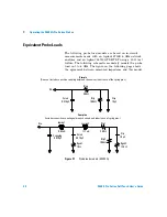
Equivalent Probe Loads
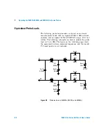
The following probe load models are based on in- circuit
measurements made with an Agilent 8753E 6 GHz network
analyzer and an Agilent 54750A TDR/TDT using a 50
Ω
test
fixture. The following schematic accurately models the probe
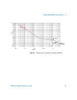
load out to 6 GHz. The figure on the following page shows
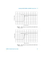
the agreement between measured impedance and this model.
Figure 21
Probe load models (E5404A)
400
Ω
Rtap
Cstub
0.375pF
Rtip
100k
Ω
Din
Ctip
10pF
250
Ω
Rtip1
1.17nH
Lspring2
0.63nH
Lspring1
Cstub
0.375pF
Rgnd1
10
Ω
Ccoupling
0.070pF
Rtip2
100k
Ω
Din
Ctip
10pF
Rgnd2
120
Ω
Complex
(Includes capacitive coupling between channels and inductance of spring pins.)
Simple
(Does not include capacitive coupling between channels or inductance of the spring pins)

