

8
Installation Note
Agilent Technologies E5346A 38-Pin Probe and E5351A 38-Pin Adapter Cable
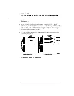
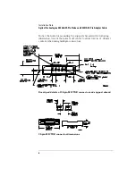
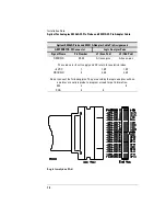
Top view surface mount receptacle
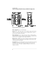
Pin 1 and pin 3.
Do not use these pins.
Pins 5, 7, 9, ... 37.
These pins are even numbered logic probe inputs.
CLKe is the clock probe input used in state analysis. D15e to D0e on
the even side are probe data inputs.
Pin 2 and pin 4.
Do not connect these pins. They are SCL and SDA,
which are used by the logic analyzer with an emulator or analysis probe
(preprocessor) to program or read target information.
Pins 6, 8, 10, ... 38.
These pins are odd numbered logic probe inputs.
CLKo is clock probe input used in state analysis. D15o to D0o on the
odd side are probe data inputs.
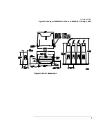
Grounds.
There are five through-hole connections that are the ground
returns for the 32 data and 2 clock probe inputs. This connection
should be made to the target’s digital ground plane as close to the
target as possible.


