

2
Installation overview
1
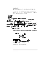
Attach the MICTOR connector(s) to the target system. Use 38-
pin surface mount receptacles, AMP part number 2-767004-2.
See Also
Refer to AMP MICTOR Application Specification 114-11004 for
guidelines on soldering. This document can be downloaded from
http://connect.amp.com/AMP/docs/pdf/6/95/158596.pdf.
2
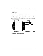
Align the MICTOR connector with the support shroud. Note pin 1
orientation for both connector and shroud.
3
Attach the support shroud around the MICTOR connector using
glue or solder. If soldering, the hole must be plated.
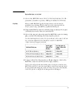
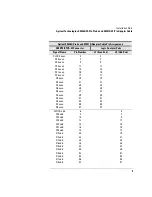
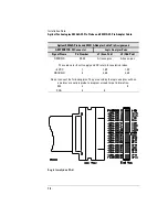
Use the following table to select the part number of the correct shroud
for your board thickness. The kits listed consist of 5 MICTOR
connectors and 5 support shrouds..
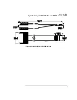
4
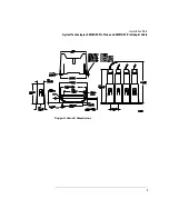
Connect either the 38-pin probe or 38-pin adapter cable to the
MICTOR connector and then to the logic analyzer.
Tabs on the support shroud lock the probe or adapter cable into the
MICTOR connector to provide dependable connections and prevent it
from inadvertently being disconnected. They also protect the flexible
end of the probe or adapter from being bent and damaged.
For Board Thickness
Use Support
Shroud Part
Number
Use Connector &
Support Shroud Kit
Number
Up to 1.575 mm (0.062 in.)
E5346-44701
E5346-68701
1.575 to 3.175 mm (0.062 to 0.125 in.)
E5346-44704
E5346-68700
3.175 to 4.318 mm (0.125 to 0.70 in.)
E5346-44703
None


