background image

Performance Tests
Instrument Accuracy Test

2-10

Agilent E4418B/E4419B Service Guide

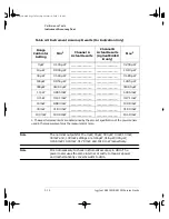
Table 2-3:  Instrument Accuracy Results (For Indication Only)

Note  

The nominal outputs for the 3

µ

W, 30

µ

W, 300

µ

W, 3 mW, 10 mW, 

30 mW and, 100 mW settings are 3.16

µ

W, 31.6

µ

W, 316

µ

W, 

3.156 mW, 10.03 mW, 31.78 mW, and 101.3 mW respectively.

Note  

It is not necessary to check instrument accuracy in dBm. The 
power meter uses the same internal circuitry to measure power 
and mathematically converts watts to dBm.

Range 

Calibrator 

Setting

Min

1

1. These performance limits are determined by the zero set specification of the power sensor 
used in the measurement plus the measurement noise.

Channel A 

Actual Results 

Channel B 

Actual Results 
(Agilent E4419

B only)

Max

1

3

µ

W

3.100 

µ

W

_______________

_______________

3.230 

µ

W

10 µ

W

9.900 

µ

W

_______________

_______________

10.10 

µ

W

30 µ

W

31.40 

µ

W

_______________

_______________

31.80 

µ

W

100 µ

W

99.50 

µ

W

_______________

_______________

100.5 

µ

W

300 µ

W

314.00 

µ

W

_______________

_______________

318.00 

µ

W

1 mW

0.995 mW

_______________

_______________

1.005 mW

3 mW

3.141 mW

_______________

_______________

3.171 mW

10 mW

9.984 mW

_______________

_______________

10.08 mW

30 mW

31.63 mW

_______________

_______________

31.94 mW

100 mW

100.9 mW

_______________

_______________

101.8 mW

4402serv.book  Page 10  Tuesday, October 14, 2003  3:18 PM

Содержание E4418B

Страница 1: ...Packard wie HP Halbleiterprodukte HP chemische Analysen oder HP Test und Messwesen nun zu der Firma Agilent Technology gehören Um Verwirrung zu vermeiden wurde lediglich bei Produktname und Nummer der vo laufende Firmenname geändert Produkte mit dem Namen Nummer HP XXXX lauten nun mehr Agilent XXXX Z B das Modell HP 8648 heißt nun Agilent 8648 Questo manuale potrebbe contenere riferimenti ad HP o ...

Страница 2: ...P または 横河 ヒューレット パッカード株式会社 とい う語句を Agilent または アジレント テクノロジー株式会社 と変更して ください ヒューレット パッカード社の電子計測 半導体製品 化学分析ビジネス部門は分 離独立し アジレント テクノロジー社となりました 社名変更に伴うお客様の混乱を避けるため 製品番号の接頭部のみ変更しておりま す 例 旧製品名 HP 4294A は 現在 Agilent 4294A として販売いたしておりま す ...

Страница 3: ...Agilent Technologies Part no E4418 90059 Revision C September 2003 Service Guide Agilent Technologies E4418B E4419B Power Meters 4402serv book Page i Tuesday October 14 2003 3 18 PM ...

Страница 4: ...1998 2003Agilent Technologies All rights reserved Reproduction adaptation or translation without prior written permission is prohibited except as allowed under the copyright laws Printed in the UK 4402serv book Page ii Tuesday October 14 2003 3 18 PM ...

Страница 5: ...ishings performance or use of this material No part of this document may be photocopied reproduced or translated to another language without the prior written consent of Agilent Technologies Certification Agilent Technologies certifies that this product met its published specifications at the time of shipment from the factory Agilent Technologies further certifies that its calibration measurements...

Страница 6: ...for the product or improper site preparation or maintenance NO OTHER WARRANTY IS EXPRESSED OR IMPLIED AGILENT TECHNOLOGIES SPECIFICALLY DISCLAIMS THE IMPLIED WARRANTIES OF MERCHANTABILITY AND FITNESS FOR A PARTICULAR PURPOSE Exclusive Remedies THE REMEDIES PROVIDED HEREIN ARE BUYER S SOLE AND EXCLUSIVE REMEDIES AGILENT SHALL NOT BE LIABLE FOR ANY DIRECT INDIRECT SPECIAL INCIDENTAL OR CONSEQUENTIAL...

Страница 7: ...s a Safety Class I product provided with a protective earthing ground incorporated in the power cord The mains plug shall only be inserted in a socket outlet provided with a protective earth contact Any interruption of the protective conductor inside or outside the instrument is likely to make the instrument dangerous Intentional interruption is prohibited If this instrument is not used as specifi...

Страница 8: ...rained service personnel Markings The CE mark shows that the product complies with all the relevant European legal Directives if accompanied by a year it signifies when the design was proven This is the symbol of an Industrial Scientific and Medical Group 1 Class A product The CSA mark is a registered trademark of the Canadian Standards Association External Protective Earth Terminal While this is ...

Страница 9: ...compliance with IEC 60529 1989 Degrees of Protection Provided by Enclosures IP Code Level IPx4 is attained if and only if the carry case Agilent part number 34141A is fitted User Environment This product is designed for use in a sheltered environment avoiding extreme weather conditions in accordance with Pollution Degree 3 defined in IEC 60664 1 with the carry case Agilent part number 34141A fitte...

Страница 10: ... German Language User s Guide Option ABD Spanish Language User s Guide Option ABE French Language User s Guide Option ABF Italian Language User s Guide Option ABZ Japanese Language User s Guide Option ABJ Agilent E4418B E4419B Service Guide is available by ordering Option 915 Agilent E4418B E4419B CLIPs Component Location and Information Pack is available by ordering E4418 90031 4402serv book Page...

Страница 11: ...s 19 F Cityplaza One 1111 King s Road Taikoo Shing Hong Kong SAR tel 852 2599 7889 fax 852 2506 9233 Japan Agilent Technologies Japan Ltd Measurement Assistance Center 9 1 Takakura Cho Hachioji Shi Yokyo 192 8510 tel 81 426 56 7832 fax 81 426 56 7840 Australia New Zealand Agilent Technologies Australia Pty Ltd 347 Burwood Highway Forest Hill Victoria 3131 tel 1 800 629 485 Australia fax 61 3 9272 ...

Страница 12: ...Suite 950 Miami Florida 33126 U S A tel 305 267 4245 fax 305 267 4286 United States Agilent Technologies Test and Measurement Call Center P O Box 4026 Englewood CO 80155 4026 tel 1 800 829 4444 In any correspondence or telephone conversations refer to the power sensor by its model number and full serial number With this information the Agilent Technologies representative can quickly determine whet...

Страница 13: ...damage by generating static electricity and by lodging in the rear panel 2 Use the original packaging materials or a strong shipping container that is made of double walled corrugated cardboard with 159 kg 350 lb bursting strength The carton must be both large enough and strong enough to accommodate the power meter and allow at least 3 to 4 inches on all sides of the power meter for packing materi...

Страница 14: ...erformance of the power meter Chapter 4 Theory of Operation This chapter describes how each of the power meter s individual assemblies operate Chapter 5 Replaceable Parts This chapter details the power meter s replaceable parts It also explains how to assemble and disassemble the power meter Chapter 6 Troubleshooting This chapter contains troubleshooting flow charts designed to isolate faults in t...

Страница 15: ...ion 001 Operational Characteristics 1 13 General Characteristics 1 14 Rear Panel Connectors 1 14 Environmental Characteristics 1 15 General Conditions 1 15 Operating Environment 1 15 Storage Conditions 1 15 General 1 16 Dimensions 1 16 Weight 1 16 Safety 1 16 Remote Programming 1 17 Non Volatile Memory 1 17 Performance Tests 1 Introduction 2 2 Equipment Required 2 3 Performance Test Record 2 4 Per...

Страница 16: ...2 17 Agilent E Series Power Sensor Interface Test 2 19 Procedure 2 19 Agilent E Series Power Sensor Functional Test 2 20 Description 2 20 Equipment 2 20 Procedure 2 20 Output Standing Wave Ratio SWR Test 2 23 Specification 2 23 Description 2 23 Equipment 2 25 Test Setup 2 25 Procedure 2 25 Performance Test Record 2 30 Adjustments 1 Introduction 3 2 Safety Considerations 3 2 Equipment Required 3 3 ...

Страница 17: ...onnector Repair 5 6 Firmware Upgrades 5 7 Downloading Firmware 5 7 Assembly and Disassembly Guidelines 5 8 Removing the Power Meter Cover 5 8 Removing the A1 Power Supply Assembly 5 9 Removing the A2 Processor Assembly 5 10 Removing the A4 Comms Assembly 5 11 Removing the A5 Daughter or A6 Measurement Assemblies5 12 Removing the A7 Fan Assembly 5 13 Removing the Power Meter RAM Battery BT1 5 14 Re...

Страница 18: ...tandard Uncertainty uc y A 9 Expanded Uncertainty kuc y A 9 Measurement Uncertainty Analysis Power Reference Level Test1 Measurement Introduction B 2 Define the Measurand B 2 Define the Measurement Equation B 2 Uncertainty Equation B 4 Voltage Measurements Uncertainty B 4 Mismatch B 5 Calibration factor B 7 Sensor Calibration Factor Drift B 7 Resistance B 8 Repeatability B 8 Sensitivity Coefficien...

Страница 19: ...1 Specifications 4402serv book Page 1 Tuesday October 14 2003 3 18 PM ...

Страница 20: ...ise stated and after performing a zero and calibration Supplemental characteristics which are shown in italics are intended to provide information useful in applying the power meter by giving typical but non warranted performance parameters These characteristics are shown in italics or denoted as typical nominal or approximate For information on measurement uncertainty calculations refer to Agilen...

Страница 21: ...s power sensors and Agilent E series power sensors Single Sensor Dynamic Range 90 dB maximum Agilent E series power sensors 50 dB maximum Agilent 8480 series power sensors Display Units Absolute Watts or dBm Relative Percent or dB Display Resolution Selectable resolution of 1 0 0 1 0 01 and 0 001 dB in logarithmic mode or 1 2 3 and 4 significant digits in linear mode Default Resolution 0 01 dB in ...

Страница 22: ... refer to Table 1 1 For Agilent E series power sensors this specification applies when zeroing is performed with the sensor input disconnected from the POWER REF Table 1 1 Zero Set Specifications Power Sensor Zero Set Agilent 8481A 50 nW Agilent 8481B 50 µW Agilent 8481D 20 pW Agilent 8481H 5 µW Agilent 8482A 50 nW Agilent 8482B 50 µW Agilent 8482H 5 µW Agilent 8483A 50 nW Agilent 8485A 50 nW Agil...

Страница 23: ...es of the Metre Convention such as the National Institute of Standards and Technology in the USA are signatories to the Comité International des Poids et Mesures Mutual Recognition Arrangement Further information is available from the Bureau International des Poids et Mesures at http www bipm fr 2 This SWR specification is only warranted for the E4418B and the E4419B Power Meters with serial prefi...

Страница 24: ...s are available as shown along with the typical maximum measurement speed for each mode Normal 20 readings second x2 40 readings second Fast 200 readings second for Agilent E series power sensors only Maximum measurement speed is obtained using binary output in free run trigger mode Zero Drift of Sensors Power sensor dependent refer to Table 1 3 4402serv book Page 6 Tuesday October 14 2003 3 18 PM...

Страница 25: ...ode and 32 for x2 mode Use the Noise Multiplier for the appropriate mode normal or x2 and number of averages to determine the total measurement noise value For example for an Agilent 8481D power sensor in normal mode with the number of averages set to 4 the measurement noise is equal to 45 pW x 2 75 124 pW Table 1 2 Noise Multiplier Number of Averages 1 2 4 8 16 32 64 128 256 512 1024 Noise Multip...

Страница 26: ...easurement noise is measured within the low range Refer to the relevant power sensor manual for further information Agilent 8481A 10 nW 110 nW Agilent 8481B 10 µW 110 µW Agilent 8481D 4 pW 45 pW Agilent 8481H 1 µW 10 µW Agilent 8482A 10 nW 110 nW Agilent 8482B 10 µW 110 µW Agilent 8482H 1 µW 10 µW Agilent 8483A 10 nW 110 nW Agilent 8485A 10 nW 110 nW Agilent 8485D 4 pW 45 pW Agilent R8486A 10 nW 1...

Страница 27: ...e 0 15 0 18 0 22 0 35 0 55 1 1 1 9 3 5 6 9 14 5 33 10 dB 10 dB 10 dB 20 dB Maximum dBm Minimum dBm Power 150 ms 6 6 s 500 ms 200 ms Settling Times Sensor Dynamic Range 10 dB 10 dB 10 dB 20 dB Maximum dBm Minimum dBm Power Settling Times Sensor Dynamic Range 10 dB 10 dB 10 dB 20 dB Maximum dBm Minimum dBm Power Settling Times Sensor Dynamic Range 10 dB 10 dB 10 dB 20 dB Power 150 ms 3 5 s 350 ms 18...

Страница 28: ...g power step crosses the power sensor s auto range switch point add 25 ms Refer to the relevant power sensor manual for further information For Agilent E series power sensors in normal and x2 speed modes manual filter 10 dB decreasing power step Table 1 5 Settling Time Number of Averages 1 2 4 8 16 32 64 128 256 512 1024 Settling Time s Normal Mode 0 07 0 12 0 21 0 4 1 1 8 3 3 6 5 13 27 57 Respons...

Страница 29: ... step normal and x2 speed modes 10 dB 10 dB 10 dB 60 dB Maximum dBm Minimum dBm Power Sensor 40 ms 3 4 s 210 ms 70 ms Settling Times Typical Dynamic Range 10 dB 10 dB 10 dB 60 dB Maximum dBm Minimum dBm Power Sensor 70 ms 6 5 s 400 ms 120 ms Settling Times Typical Dynamic Range Normal Mode x2 Mode 4402serv book Page 11 Tuesday October 14 2003 3 18 PM ...

Страница 30: ... for residual offsets Zero Drift This parameter is also called long term stability and is the change in the power meter indication over a long time usually one hour for a constant input power at a constant temperature after a defined warm up interval Measurement Noise This parameter is also known as short term stability and is specified as the change in the power meter indication over a short time...

Страница 31: ... is not covered by the product warranty Typical Operating Time Up to 2 hours with LED backlight on up to 3 hours with LED backlight off Charge Time 2 hours to charge fully from an empty state 50 minutes charging enables 1 hour of operation with LED backlight ON 35 minutes charging enables 1 hour of operation with the LED backlight OFF Power meter is operational whilst charging Service Life To 70 o...

Страница 32: ...nnector Remote Input Output A TTL logic level is output when the measurement exceeds a predetermined limit TTL inputs are provided to initiate zero and calibration cycles RJ 45 series shielded modular jack assembly TTL output high 4 8 V max low 0 2 V max TTL input high 3 5 V min 5 V max low 1 V max 0 3 V min Ground Binding post accepts 4 mm plug or bare wire connection Line Power Input Voltage Ran...

Страница 33: ...iated Interference Standard EN 55011 1991 CISPR11 1990 Group 1 Class A Operating Environment Temperature 0ºC to 55ºC Maximum Humidity 95 at 40ºC non condensing Minimum Humidity 15 at 40ºC non condensing Maximum Altitude 3 000 meters 9 840 feet Storage Conditions Storage Temperature 20ºC to 70ºC Non Operating Maximum Humidity 90 at 65ºC non condensing Non Operating Maximum Altitude 15 240 meters 50...

Страница 34: ...kg 11 0 lb with option 001 Agilent E4419B 4 1 kg 9 0 lb 5 1 kg 11 2 lb with option 001 Shipping Agilent E4418B 7 9 kg 17 4 lb 8 9 kg 19 6 lb with option 001 Agilent E4419B 8 0 kg 17 6 ib 9 0 kg 19 8 lb with option 001 Safety Conforms to the following Product Specifications EN61010 1 1993 IEC 1010 1 1990 A1 CSA C22 2 No 1010 1 1993 EN60825 1 1994 IEC 825 1 1993 Class 1 Low Voltage Directive 72 23 E...

Страница 35: ...tandard Command Language SCPI standard interface commands Agilent E4418B is HP 437B code compatible Agilent E4419B is HP 438A code compatible Agilent E4418B E4419B GP IB Compatibility SH1 AH1 T6 TE0 L4 LE0 SR1 RL1 PP1 DC1 DT1 C0 Non Volatile Memory Battery Lithium Polycarbon Monoflouride approximate lifetime 5 years at 25ºC 4402serv book Page 17 Tuesday October 14 2003 3 18 PM ...

Страница 36: ...Specifications General 1 18 Agilent E4418B E4419B Service Guide 4402serv book Page 18 Tuesday October 14 2003 3 18 PM ...

Страница 37: ...2 Performance Tests 4402serv book Page 1 Tuesday October 14 2003 3 18 PM ...

Страница 38: ... to the interior of the power meter A simpler operational test is included in Self Test of the User s Guide Note For valid performance tests the following conditions must be met a The power meter and test equipment must have a 30 minute warm up for all specifications b The line voltage for the power meter must be 85 to 264 Vac and the line frequency must be 50 to 440 Hz c The ambient temperature m...

Страница 39: ...0A or Fluke 5720A P Range Calibrator Agilent 11683A or Agilent 11683A Opt H01 Option H01 is essential for accurate verification See analysis in Appendix A The Standard 11683A can be used for indication only P Frequency Counter Agilent 53132A Range 10 Hz to 50 MHz Resolution 1 Hz P and A Power Meter Agilent 432A Range 1 mW Transfer Accuracy 0 2 P and A Thermistor Mount Agilent 478A Opt H75 H76 or A...

Страница 40: ...igned to verify published power meter specifications Perform the tests in the order given and record the data in Table 2 8 on page 2 30 and or in the data spaces provided at the end of each procedure Calibration Cycle This power meter requires periodic verification of performance to ensure that it is operating within specified tolerances The performance tests described in this chapter should be pe...

Страница 41: ...st Setup Electrical Characteristics Performance Limits Accuracy Zero set Digital settability of zero 0 0764 µW1 1 This performance limit is determined by the zero set specification of the power sensor used in the measurement plus the measurement noise The range calibrator has a zero set specification of 0 05 µW The calibrator measurement noise specification is 110 nW at 16 averages At 512 averages...

Страница 42: ...ro value before attempting to zero the power meter This settling would appear on the power meter display as downward drift When the drift has reached minimum typically less than 60 seconds the range calibrator is settled 6 On the power meter press and set the filter length to 512 in the pop up window then press 7 On the power meter press Wait approximately 10 seconds for the wait symbol to disappe...

Страница 43: ...values associated with it Test Procedure 1 Note The measurement uncertainty of this test procedure is relatively high at power levels of 30uW and below as it uses a standard 11683A Range Calibrator As such this test procedure should be used for indication only Equipment Range Calibrator Agilent 11683A Power Sensor Cable Agilent 11730A Electrical Characteristics Performance Limits Accuracy 0 5 or 0...

Страница 44: ...uired on the Agilent E4418B For the Agilent E4419B the equivalent key presses should be performed on both channels 1 Connect the equipment as shown in Figure 2 2 2 Switch the power meter on 3 Press then 4 Press for a reading in watts 5 Set the range calibrator as follows RANGE 3 µW POLARITY NORMAL FUNCTION STANDBY LINE ON Agilent 11730A POWER METER CHANNEL A Power Meter Range Calibrator Preset Loc...

Страница 45: ...t the filter length to 512 in the pop up window then press 7 On the power meter press Wait approximately 10 seconds for the wait symbol to disappear Verify that the display reads 0 0 05 µW 8 Set the range calibrator s FUNCTION switch to CALIBRATE 9 Set the range calibrator s RANGE switch to 1 mW 10 Press to calibrate the power meter 11 Set the range calibrator s RANGE switch to the positions shown...

Страница 46: ...ification of the power sensor used in the measurement plus the measurement noise Channel A Actual Results Channel B Actual Results Agilent E4419 B only Max1 3 µW 3 100 µW _______________ _______________ 3 230 µW 10 µW 9 900 µW _______________ _______________ 10 10 µW 30 µW 31 40 µW _______________ _______________ 31 80 µW 100 µW 99 50 µW _______________ _______________ 100 5 µW 300 µW 314 00 µW __...

Страница 47: ...hod refer to Appendix A for a description of the measurement uncertainty analysis As such this test procedure should be used to ensure the power meter meets it s published specification Equipment Range Calibrator Agilent 11683A Option H01 Power Sensor Cable Agilent 11730A DC Range Calibrator Datron 4000A Test Setup Figure 2 3 Instrument Accuracy Average Path Test Setup Power Meter CHANNEL A Power ...

Страница 48: ...operate with no power applied and disconnecting the power cord eliminates the problem WARNING There is a small risk of mild electrical shock from the chassis of the 11683A option H01 range calibrator unless the power meter is connected 3 Figure 2 3 shows the HI LO outputs of the DC calibrator connected to the DC reference input of the range calibrator Ensure that the Guard and LO output of the DC ...

Страница 49: ... the range calibrator is settled 9 Set the DC calibrator as follows SET VALUE 0 ZERO FUNCTION DC OUTPUT OFF 10 On the power meter press and set the filter length to 512 in the pop up window then press 11 On the power meter press Wait approximately 10 seconds for the wait symbol to disappear Verify that the display reads 0 0 05 µW 12 Set the DC calibrator output to 144 93mV and set the output switc...

Страница 50: ...es Table 2 4 Instrument Accuracy Results DC Calibrator Setting Effective Power Applied Power Meter Filter Setting Meas Unc Lower Limit Ch A Result Ch B Result Upper Limit 458 31uV 3 1623 uW 256 0 028 uW 3 0977uW 3 2269uW 1 4493mV 10uW 256 0 027 uW 9 904 uW 10 096uW 4 5831mV 31 6228uW 256 0 027 uW 31 428uW 31 819uW 14 493mV 100uW 64 0 073 uW 99 49uW 100 51uW 45 831mV 316 2278uW 64 0 104 uW 314 72uW...

Страница 51: ...ccuracy is determined from the system measurement uncertainty plus any chosen test line limit For example if a test line limit of 1 mW 0 2 was chosen while maintaining a system measurement uncertainty of 0 3 the overall accuracy of the test setup for the 1 mW power output becomes 0 3 0 2 giving a setting accuracy of 0 5 Electrical Characteristics Performance Limits Conditions Power reference 1 mW ...

Страница 52: ...e following procedure ensures maximum accuracy in measuring power reference oscillator output using Agilent test instruments of known capability Signal acquisition criteria may vary if alternative test instruments are used In such cases refer to the manufacturer s guidelines for further information The test is performed using Equation 2 4 Equation 2 4 Power Level Provided By The Reference Oscillat...

Страница 53: ...nect the DVM between the VRF connector on the rear panel of the Agilent 432A and pin 1 on the thermistor mount end of the sensor cable Verify that no power is applied to the Agilent 432A 2 Round off the DVM reading to two decimal places and note this value as the internal bridge resistance R of the Agilent 432A approximately 200 Ω R ____________Ω 3 Connect the equipment as shown in Figure 2 4 ensu...

Страница 54: ... and adjust the Coarse Zero control so that the DVM indicates 200 µV or less Release the Fine Zero switch and proceed to the next step 9 Round the DVM reading to two decimal places Record this reading as V0 V0 ___________ 10 Turn the power reference on Press 11 Round the DVM reading to two decimal places Record this reading as V1 V1 ___________ 12 Disconnect the DVM negative input lead from the VR...

Страница 55: ...er meter this test should be performed on both channels Procedure 1 When there is no power sensor connected to the Channel A input the message No Sensor No Sensor ChA on the Agilent E4419B appears on the measurement window 2 Connect the Agilent E series power sensor to the power meter s Channel A input The message Reading Sensor ChA appears When all the data is downloaded this message disappears a...

Страница 56: ...hin the range of voltages available from the Agilent 11683A range calibrator Equipment Power Sensor Cable Agilent 11730A Reference Attenuator Agilent 11708A Agilent E series power sensor Procedure To complete the Functional Test the following procedure should be performed Note The procedure details the key presses required on the Agilent E4418B For the Agilent E4419B the equivalent key presses sho...

Страница 57: ... display reads 30 dBm 1 dB Record the reading 9 Press and set to UPPER This switches to the power sensor s upper range 10 Verify that the display reads 30 dBm 1 dB Record the reading 11 Press and set to LOWER 12 Disconnect the 30 dB attenuator and reconnect as shown in Figure 2 5 13 Verify that an overload error is displayed on the status line at the top of the power meter s display 14 Press and s...

Страница 58: ...ilent E4418B E4419B Service Guide Table 2 6 Functional Test Result Test Channel A Overload Error Channel B Overload Error Agilent E4419B Only Low Range 30 dB pad Upper Range 30 dB pad Low Range no pad High Range no pad 4402serv book Page 22 Tuesday October 14 2003 3 18 PM ...

Страница 59: ... follows Equation 2 5 Power Absorbed By The Load Where PZO is the power that the source will deliver to a matched load ΓS and ΓL are the VRCs of the source and load respectively This method for measuring the source match exploits this relationship by presenting the source with two different values of ΓL and measuring the power delivered to the load under the two conditions The load used is a Elect...

Страница 60: ...he two reflection coefficients are Γ1 and Γ2 and these give the power measurements of P1 and P2 respectively but the available power remains the same then the two relationships can be equated as follows Equation 2 6 Therefore Equation 2 7 The left side of the equation can be replaced by the factor M as follows Equation 2 8 This cannot be directly solved for ΓS because it is a complex quantity In o...

Страница 61: ...on 1 Record the input VRC magnitude of the thermistor mount at 50 MHz with the Agilent 432A power meter set to 200Ω R1 ___________ 2 Record the input VRC magnitude of the thermistor mount at 50 MHz with the Agilent 432A power meter set to 100Ω R2 ___________ 3 Set the Agilent 432A mount resistance switch to 200Ω 4 Set the DVM to measure resistance Connect the DVM between the VRF connector on the r...

Страница 62: ...0 Preset the power meter Press then on the power meter Set the Agilent 432A RANGE switch to Coarse Zero Adjust the front panel Coarse Zero control to obtain a zero meter indication 11 Zero the Agilent 432A test power meter Fine zero the Agilent 432A on the most sensitive range Set the RANGE switch to 1 mW 12 Set the DVM to measure microvolts 13 Connect the positive and negative input leads to the ...

Страница 63: ...g equation 2 9 Equation 2 9 22 Record the value P1 P1 ___________ 23 Calculate the power measured with mount resistance set to 100Ω Set the Agilent 432A mount resistance switch to 100Ω Connect the equipment as shown in Figure 2 7 ensuring that the DVM input leads are isolated from chassis ground Repeat steps 15 to 20 Record the new values of V0 V1 and Vcomp V0 ___________ V1 ___________ Vcomp ____...

Страница 64: ...Equation 2 12 One of the roots of this equation will be non physical while the other gives a value for Γs Γs ___________ 27 Calculate the value of the output SWR using Equation 2 13 and record the value Equation 2 13 Output SWR ___________ 28 Verify that the output SWR is not greater than the maximum value shown in the following table Where M P1 P2 1 Γ2 2 1 Γ1 2 Where Γs 2 Γ1 M 2 Γ2 2 Γ2 2 Γ1 M 2 ...

Страница 65: ...x Actual Result 1 061 1 082 1 For instruments with the 50MHz 1mW output power ref connector mounted on the front panel 2 For instruments with the 50MHz 1mW output power ref connector mounted on the rear panel This applies to models E4418B and E4419B with option 003 fitted 4402serv book Page 29 Tuesday October 14 2003 3 18 PM ...

Страница 66: ...7 mW 99 54 mW ___________ ___________ ___________ ___________ ___________ ___________ ___________ ___________ ___________ ___________ ___________ ___________ ___________ ___________ ___________ ___________ ___________ ___________ ___________ ___________ 3 2269 µW 10 096 µW 31 819 µW 100 51 µW 317 74 µW 1 0047 mW 3 1769 mW 10 046 mW 31 769 mW 100 46 mW Power Reference Pmeas 0 999 mW ___________ ___...

Страница 67: ...nel related 2 For instruments with the 50MHz 1mW output power ref connector mounted on the front panel 3 For instruments with the 50MHz 1mW output power ref connector mounted on the rear panel This applies to models E4418B and E4419B with option 003 fitted Test Min Result Channel A Actual Result Channel B Actual Result Max Result 4402serv book Page 31 Tuesday October 14 2003 3 18 PM ...

Страница 68: ...Performance Tests Performance Test Record 2 32 Agilent E4418B E4419B Service Guide 4402serv book Page 32 Tuesday October 14 2003 3 18 PM ...

Страница 69: ...3 Adjustments 4402serv book Page 1 Tuesday October 14 2003 3 18 PM ...

Страница 70: ... are required Allow 30 minutes for the power meter to warm up and then remove the cover for access to the test and adjustment points To determine which performance tests and adjustments to perform after a repair see Post Repair Adjustments on page 3 3 Safety Considerations This warning must be followed for your protection and to avoid damage to the equipment being used WARNING Adjustments describe...

Страница 71: ...ts or Self Tests A1 Power Supply Self Test A2 Processor Assembly Frequency and Level Adjustments Power Reference Level Test Display Brightness and Contrast Adjustment A3 Front Panel Assembly Instrument Accuracy Test Display Brightness and Contrast Adjustment A4 Comms Assembly All automated Tests and Serial Interface Self Test A5 Daughter Assembly Instrument Accuracy Test A6 Measurement Assembly Ze...

Страница 72: ... on page 3 6 The power reference oscillator frequency is a nominal specification Description Variable inductor A2L9 is adjusted to set the power reference oscillator output frequency to 50 0 0 5 MHz This frequency is a supplemental characteristic Figure 3 1 Adjustment Setup Equipment Frequency Counter Agilent 53132A Procedure 1 Ensure that the power meter has been powered on for at least 30 minute...

Страница 73: ...cillator frequency is necessary If it is not within these limits adjust the power reference oscillator frequency as described in step 5 and step 6 5 Remove the power meter cover 6 Adjust A2L9 to obtain a 50 0 0 5 MHz indication on the frequency counter Refer to Figure 3 2 for the position of A2L9 Figure 3 2 A2L9 Adjustment Location Zero Cal Power Ref Off On Zero Cal Cal More Power Ref Off On BT1 A...

Страница 74: ...ent measurement system is employed for post factory test the power reference oscillator output can again be set to 1 mW 0 4 This setting is sufficient to ensure that the power reference oscillator meets the accuracy specification of 0 5 after 2 years This specification includes the 0 4 setting and also takes into account other factors that will contribute to determining the accuracy after 2 years ...

Страница 75: ...lated to give the following Equation 2 by using the following assumptions The error in doing this is So if that is then the error can be ignored In practice and The error is less than 0 01 Power Meter Agilent 432A Power Meter VRF Vcomp Thermistor Digital Voltmeter Power ref INPUT INPUT Mount Pmeas 2Vcomp V1 V0 V0 2 V1 2 4R CalibrationFactor V1 Vcomp V0 Vcomp 2 10 3 4R CalibrationFactor V0 2 V1 2 V...

Страница 76: ...tor is the value of the thermistor mount at 50 MHz Equipment Test power meter Agilent 432A Thermistor Mount Agilent 478A Option H75 or H76 Digital Voltmeter DVM Agilent 3458A Procedure Note The procedure details the key presses required on the Agilent E4418B For the Agilent E4419B the equivalent key presses should be performed on both channels 1 Set up the DVM to measure resistance Connect the DVM...

Страница 77: ...e rear panel of the Agilent 432A 8 Observe the reading on the DVM If less than 400 µV proceed with the next step If 400 µV or greater press and hold the Agilent 432A fine zero switch and adjust the coarse zero control so that the DVM indicates 200 µV or less Then release the fine zero switch and proceed to the next step 9 Round off the DVM reading to the nearest microvolt and record this value as ...

Страница 78: ...2R90 until the DVM indicates the calculated value of V1 Refer to Figure 3 4 for the position of A2R90 Figure 3 4 A2R90 Adjustment Location Measurement Uncertainty Refer to Appendix B Measurement Uncertainty Analysis Power Reference Level Test BT1 A2R90 A2L9 A2J13 J12 Front Panel A2 Assembly 4402serv book Page 10 Tuesday October 14 2003 3 18 PM ...

Страница 79: ...lly after executing the softkey located under the softkey menu Note The contrast adjustment is subjective and varies according to individual user requirements Procedure 1 Access the softkey menu and use the softkey to increase the contrast or the softkey to decrease the contrast of the display 2 When the desired display contrast level is obtained press the softkey located under the softkey menu Se...

Страница 80: ...Adjustments Display Brightness and Contrast Adjustment 3 12 Agilent E4418B E4419B Service Guide 4402serv book Page 12 Tuesday October 14 2003 3 18 PM ...

Страница 81: ...4 Theory of Operation 4402serv book Page 1 Tuesday October 14 2003 3 18 PM ...

Страница 82: ...ervice Guide Introduction This chapter describes how each of the power meter s assemblies operate A block diagram is included at the end of the chapter giving you an overall view of the power meter s operation 4402serv book Page 2 Tuesday October 14 2003 3 18 PM ...

Страница 83: ...ng current for the rechargeable battery module is independent of the state of the Power_on line A logic low on the Power_on line indicates that the front panel POWER switch is in standby mode and the three dc voltage outputs from the power supply are disabled A logic high on this line indicates that the POWER switch is in the On mode and the three dc voltages from the power supply are enabled Powe...

Страница 84: ...s fitted and the meter is in standby and connected to the ac power supply the rechargeable battery will recharge and the fan will be powered on The reference oscillator has a 50 MHz oscillator circuit with automatic level control ALC The oscillator output is level detected and that level is compared to a temperature stable precision reference voltage This comparison produces an error signal that g...

Страница 85: ...ocontroller allows the optimum backlight brightness to be factory set The temperature sense voltage LED current and LCD bias voltage are all measured at self test An analog multiplexer provides means by which several diagnostic points can be switched to the A6 measurement assembly s for analogue to digital conversion The microcontroller uses this function to perform self test A6 measurement assemb...

Страница 86: ... A4 interface assembly and the A5 daughter assembly The program memory for the microcontroller is FLASH EEPROM to allow for in circuit programming The static RAM is split into volatile and non volatile blocks with the power for the non volatile RAM being connected to the permanent battery backed power supply Note It is advisable to replace the RAM battery A2BT1 every three years If the battery fai...

Страница 87: ... assembly and a sensor cable assembly s There are two inputs to the front panel assembly the flex circuit from connector A2J4 of the processor assembly which controls the keypad the ribbon cable from A2J3 of the processor assembly which controls the LCD display The power meter self tests contain display tests These are accessed by pressing System Inputs More Service Self Test Individual Display 44...

Страница 88: ...hronous Receiver Transceiver UART integrated circuit and a programmable transceiver The programmable transceiver can be configured for either RS232 or RS422 The remote interface is designated a DTE Data Terminal Equipment The programmable baud rate generator in the UART is driven from the system clock 16 67 MHz which allows baud rates in the range 50 to 115 2 K The whole assembly is connected to d...

Страница 89: ... the rechargeable battery assembly and the A1 power supply charger assembly and provide an interface for the signal lines that are monitored by the A2 processor assembly a 48 way connector provides the interface for the A2 processor assembly signals a 36 way slotted post connector provides the interface for the A6 measurement assembly a 2 way connector for production test only The Agilent E4419B h...

Страница 90: ... power sensor produce a feedback amplifier which has a gain of approximately 500 The Feedback line shown sets the gain and also biases the transistor The differential amplifier removes any common mode noise or interference It uses a special ground wire Sensor Ground connected close to the RF bulkhead in the power sensor as it s second input The band pass filter represents the filtering action of t...

Страница 91: ... the power meter s self test of both the measurement assembly and the A2 processor assembly The results are reported back to the A2 processor assembly via the Internal Serial Bus The Agilent E series power sensors have built in serial EEPROM and range switching which is controlled or accessed via the measurement assembly The N Chop sensor wire used by the Agilent 8480 series power sensors doubles ...

Страница 92: ...or assembly on battery pack status information such as amount of charge remaining When there is less than 10 minutes run time charge remaining in the battery an error message Battery Power Low is displayed on the power meter front panel display The battery assembly can only be recharged when fitted to a power meter with the battery option fitted The charge current from the charging circuit is cont...

Страница 93: ...Theory of Operation A8 Rechargeable Battery Assembly Agilent E4418B E4419B Service Guide 4 13 Remove this page and replace with pullout fm 4402serv book Page 13 Tuesday October 14 2003 3 18 PM ...

Страница 94: ...Theory of Operation A8 Rechargeable Battery Assembly 4 14 Agilent E4418B E4419B Service Guide 4402serv book Page 14 Tuesday October 14 2003 3 18 PM ...

Страница 95: ...5 Replaceable Parts 4402serv book Page 1 Tuesday October 14 2003 3 18 PM ...

Страница 96: ...dered from Agilent Technologies It also details how to assemble and disassemble the power meter for repair To order parts contact your local Agilent Technologies Sales and Service Office To return your power meter for servicing at a qualified service center refer to Contacting Agilent Technologies in chapter 2 of the User s Guide 4402serv book Page 2 Tuesday October 14 2003 3 18 PM ...

Страница 97: ...ply and Charger Assembly Option 001 0950 3681 A2 Processor Assembly Kit New E4418 60031 Refurbished E4418 69028 A301 Front Panel Assembly for Agilent E4418B and Agilent E4418B Option 002 New E4418 61030 Refurbished E4418 69030 A302 Front Panel Assembly for Agilent E4418B Option 003 New E4418 61031 Refurbished E4418 69031 A303 Front Panel Assembly for Agilent E4419B and Agilent E4419B Option 002 Ne...

Страница 98: ...attery 1420 0338 BT2 Rechargeable Battery Opt 001 E9287A MP1 Bail Handle 34401 45011 MP2 Front Bumper 34401 86011 MP3 Rear Bumper 34401 86012 MP4 Outer Cover for Agilent E4418 9B Agilent E4418 9B Option 001 E4418 61027 E4418 61016 MP5 Rear Bezel E4418 20008 MP6 Instrument Chassis Assembly Includes push fit line module E4418 61025 MP6J1 Push Fit Line Module E4418 61002 Battery Module Cover E4418 61...

Страница 99: ...e 5 1 and Figure 5 2 and select the appropriate model The J2 connector is found nearest the fan assembly Figure 5 1 0950 2649 Power Supply Assembly Figure 5 2 0950 3681 Power Supply and Charger Assembly Front Power Reference Cable Kit E4418 61811 Rear Power Reference Cable Kit E4418 61813 Reference Designator Description Agilent Part Number 4402serv book Page 5 Tuesday October 14 2003 3 18 PM ...

Страница 100: ...exchange assembly However if front panel sensor cables or power reference cables are faulty they should be replaced by ordering the appropriate kit and following the assembly disassembly procedure The instrument accuracy test should then be carried out to verify the functionality of the new part 4402serv book Page 6 Tuesday October 14 2003 3 18 PM ...

Страница 101: ...ack The firmware can be upgraded via the GP IB connector or the serial RS232 422 connector To determine the firmware version in your power meter press Contact your local Service Center if you require a firmware upgrade Refer to Sales and Service Offices on page ix for details of your local Service Center Downloading Firmware Instrument Firmware should be downloaded after the processor board is rep...

Страница 102: ...er meter and Equipment Operation on page v before operating this power meter with the cover removed Failure to comply with the safety precautions can result in severe or fatal injury WARNING Before carrying out any assembly or disassembly of the power meter ensure that you disconnect the power cord Even with the power meter switched off there are potentially dangerous voltages present on the power...

Страница 103: ...n T15 screw driver WARNING When replacing the power supply unit in the power meter ensure that all earth wiring is reconnected There are two terminals to check The first is the force fit connector to the power supply unit itself It is essential that the gap between the terminal and the adjacent large capacitor is maximized Fit the connector so that its flat side faces towards the large capacitor T...

Страница 104: ...move the three screws as shown When replacing these screws use a 6 lb in T10 screw driver 5 Push the A2 processor assembly towards the front panel to release it from the 50 pin connector Lift it upwards to remove Note When re assembling the processor board ensure the A2 plastic support bracket is returned to its locked position Note After replacing a processor board the Power Reference Frequency a...

Страница 105: ... screw driver 4 Remove the two screws on the underside of the deck assembly Remove the assembly by sliding forward and tilting up from the rear when replacing these screws use a 21 lb in T15 screw driver 5 Unscrew the GP IB and RS232 422 connectors from the rear panel When replacing these screws use a 6 lb in 9 32 in socket 6 Disconnect the Recorder cable for channel A from J23 pins 1 2 3 Disconne...

Страница 106: ... connector tab forward and lifting To replace the flex circuit loop it as shown on page 5 17 and connect the flex circuit as shown in the figures below 2 Slide out the measurement assembly from the side of the power meter 3 The daughter assembly is removed vertically A5 A6 1 Connector closed 2 Slide connector clamp in direction of arrow 3 Rotate connector 4 Position sensor flex circuit into connec...

Страница 107: ...ide 5 13 Removing the A7 Fan Assembly 1 Remove the A1 power supply assembly as shown on page 5 9 2 Remove the pins which attach the fan to the chassis 3 Remove the fan cable connector from the A2 processor assembly to release the fan 4402serv book Page 13 Tuesday October 14 2003 3 18 PM ...

Страница 108: ...e battery is siliconed to the assembly It may be necessary to remove it using a scalpel 5 Store the battery individually in an anti static dissipative bag or suitable non conductive packaging 6 After replacing the battery secure it using a tie wrap This should be secured from the top of the A2 processor assembly The recommended tie wrap part number is 1400 1154 7 Replace the A2J1 link WARNING This...

Страница 109: ... cable 2 Disconnect the flex circuit from the measurement assembly Note Care should be taken when disconnecting the flex circuit from the measurement assembly The flex circuit assembly is released by pushing the connector tab forward and lifting To replace the flex circuit loop it as shown on page 5 17 and connect the flex circuit as shown in the figures on page 5 12 3 Remove the center screw from...

Страница 110: ...nsor Cable Assemblies 1 Remove the front panel from the power meter Refer to Removing the A3 Front Panel Assembly on page 5 15 for details on removing the front panel 2 Replace the power sensor cable assembly s using the replacement kit Front panel sensor retaining clip recess 4402serv book Page 16 Tuesday October 14 2003 3 18 PM ...

Страница 111: ...Replaceable Parts Assembly and Disassembly Guidelines Agilent E4418B E4419B Service Guide 5 17 4402serv book Page 17 Tuesday October 14 2003 3 18 PM ...

Страница 112: ...front panel from the power meter Refer to Removing the A3 Front Panel Assembly on page 5 15 for details on removing the front panel 2 Replace the power reference output cable assembly using the replacement kit and the torques indicated on the following diagrams 25 lb in Fold up tab after assembly 9 lb in 6 lb in 4402serv book Page 18 Tuesday October 14 2003 3 18 PM ...

Страница 113: ... access to the rear panel connectors This is done by following steps 1 through 3 of the A4 comms assembly removal procedure on page 5 11 2 Replace the power sensor cable assembly s using the replacement kits The inner recess on the power sensor cable is used to locate the circlip when assembling to the rear chassis Rear panel sensor retaining clip recess 4402serv book Page 19 Tuesday October 14 20...

Страница 114: ...Replaceable Parts Assembly and Disassembly Guidelines 5 20 Agilent E4418B E4419B Service Guide 4402serv book Page 20 Tuesday October 14 2003 3 18 PM ...

Страница 115: ...ption 003 1 Disassemble the power meter down to allow access to the rear panel connectors Refer to Removing the A4 Comms Assembly on page 5 11 2 Replace the power reference cable assembly using the replacement kit and the torques indicated on the following diagrams 25 lb in 6 lb in 9 lb in tie wraps 4402serv book Page 21 Tuesday October 14 2003 3 18 PM ...

Страница 116: ...r meter down to allow access to the rear panel connectors Refer to Removing the A4 Comms Assembly on page 5 11 2 Replace the recorder output cable assembly using the replacement kit and the torque indicated on the following diagram Note Recorder output A connects to A4 J23 and recorder output B connects to A4 J24 25 lb in 4402serv book Page 22 Tuesday October 14 2003 3 18 PM ...

Страница 117: ...nits remove the Rear Panel Power Reference Connector as shown in Replacing the Rear Panel Power Reference Cable Assembly Option 003 on page 5 21 8 Remove the Recorder Output s Cable Assembly as shown on page 5 21 9 Remove all blanking plugs from the rear panel 10 Obtain the new Chassis Assembly and then re assemble the Power Meter by following steps 1 to 9 in reverse order WARNING When replacing t...

Страница 118: ...Replaceable Parts Assembly and Disassembly Guidelines 5 24 Agilent E4418B E4419B Service Guide 4402serv book Page 24 Tuesday October 14 2003 3 18 PM ...

Страница 119: ...6 Troubleshooting 4402serv book Page 1 Tuesday October 14 2003 3 18 PM ...

Страница 120: ...pable of producing 300 ms TTL single shot pulses for example Agilent 33120A 3 5 V TTL logic level source 4 RS232 self test connector 9 way D type female connector with the following pins wired together Pin 2 Rx to Pin 3 Tx Pin 4 DTR to Pin 6 DSR Pin 7 RTS to Pin 8 CTS 5 RS422 self test connector 9 way D type female connector with the following pins wired together Pin 1 CTS to Pin 9 RTS Pin2 Rx to ...

Страница 121: ...onnect Sensor to Channel A AnySensor Errors Press System Inputs More Service Self Test Instrument Self Test Self Test Errors Using DVM E2373A or equivalent End Yes No A Select Done No set to VDC monitor Rmt I O Connector pin 3 wrt pin 8 Investigate Power Meter Failure Investigate Sensor failure No Yes Yes 4402serv book Page 3 Tuesday October 14 2003 3 18 PM ...

Страница 122: ...y as directed on page 5 9 to access the Comms Assembly connector Use DVM to check resistance between J4 pin 41 and Rmt I O connector pin 3 Yes No Fault found with Upper Window TTL Over Limit detection circuit check user application implementation DVM reading 5 0V 0 5V DVM reading 0 0V 0 5V Yes No End A4 Comms Assy Defective A2 Processor Assy Defective No Select Fail O P High DVM reading 450Ω 10 No...

Страница 123: ...onnect Sensor to Channel A AnySensor Errors Select System Inputs More Service Self Test Instrument Self Test Self Test Errors Using DVM E2373A or equivalent End Yes No A Select Done No set to VDC monitor Rmt I O Connector pin 4 wrt pin 8 Investigate Power Meter Failure Investigate Sensor Failure No Yes Yes 4402serv book Page 5 Tuesday October 14 2003 3 18 PM ...

Страница 124: ...essor assy as directed on page 5 9 to access the Comms Assembly connector Use DVM to check resistance between J4 pin 42 and Rmt I O connector pin 4 Yes No Fault found with Upper Window TTL Over Limit detection circuit check user application implementation DVM reading 5 0V 0 5V DVM reading 0 0V 0 5V Yes No End A4 Comms Assy Defective A2 Processor Assy Defective No Select Fail O P High DVM reading 4...

Страница 125: ...ice Self Test Instrument Self Test Self Test Errors End Yes No A Select No Investigate Power Meter Failure Investigate Sensor Failure No Yes Yes Connect Sensor to Channel B if applicable Done Zero Cal More TTL Inputs On Apply TTL logic 0 pulse to RJ45 connector pin 5 wrt pin 8 Apply TTL logic 1 pulse to RJ45 connector pin 6 wrt pin 8 See User s Guide Ch 2 for timing 4402serv book Page 7 Tuesday Oc...

Страница 126: ...he meter single or dual channel Apply TTL logic 1 level to Rmt I O connector pin 5 wrt pin 8 Apply TTL logic 0 pulse to Rmt I O connector pin 6 wrt pin 8 See User s Guide chapter 2 for timing Did Channel B CAL No fault found with Channel B TTL Input selection Check user application implementation No fault found with Channel A Input Zero CAL selection Check user application implementation End Singl...

Страница 127: ...ations Assembly connector Measure resistance between Rmt I O connector pin 6 and connector J4 pin 43 Meter reading 470Ω 10 Measure resistance between Rmt I O connector pin 5 and connector J4 pin 44 Meter reading 470Ω 10 A2 Processor assy defective End A4 Comms assy defective No No Yes Yes 4402serv book Page 9 Tuesday October 14 2003 3 18 PM ...

Страница 128: ...rface RS232 Connect RS422 Self Test Connector to RS232 422 Connector on rear panel Select System Inputs More Service Self Test Individual More Serial Interface RS232 Loop Back Run Test Test Pass Connect power meter to a GP IB controller and send the command RST Did power meter reset Select System Inputs Remote Interface Select Interface GPIB IEEE 488 Prev Command Set SCPI No fault found with RS232...

Страница 129: ...fferent test equipment from that listed in this Service Guide However the equipment used and the Measurement Uncertainty results are similar enough to make the analysis useful For example the 11683A H01 Range Calibrator performs the same function as the modified 8482A used in this analysis Similarly the Datrron Fluke DC Calibrator performs the same function as the combined 3245 3458A setup 4402ser...

Страница 130: ...he sensor from a 3245 Universal Source The output from the universal source is measured at the head of the sensor by a 3458 DMM In effect there is now zero measurement uncertainty associated with the Universal Source as the 3458 DMM has assumed all the uncertainty In this test DC signals are injected into the modified sensor These are made in 5dB steps from 25dBm to 20dBm A conversion from voltage...

Страница 131: ... 2dBm value as being 0dBm and adjusts itself accordingly Now throughout every measurement level the 8482A and the power meter has the same 0 2dBm offset because the sensor is linear Define the Measurand The measurand is the Measurement Accuracy of the DUT Define the Measurement Equation Note Test Station Error TSE is the error contribution of the cables connectors noise and so forth that cannot be...

Страница 132: ...eter DUT in effect we are averaging out the error associated with the DUT s measurement capability leaving us with a raw test station uncertainty which is made up from TSE and the DMM error for example the Measured Voltage MV The method that is used to calculate the Measurement Uncertainty of our test station is a combination of Type A and Type B analysis in line with the ISO Expression of Measure...

Страница 133: ...lts Reference 3458A Operating Manual Appendix A Factory Traceability From 6ppm to 0 5ppm Standard Uncertainty depending on range Power Level Standard Deviation of 30 Readings Conversion to Linear Units Standard Uncertainty u X 25 3 162uW 0 0132dB 0 0097uW u X 20 10uW 0 0038dB 0 009uW u X 15 31 62uW 0 0013dB 0 0095uW u X 10 100uW 0 0015dB 0 035uW u X 5 316 2uW 0 0004dB 0 03uW u X 0 1mW 0 0003dB 0 0...

Страница 134: ...ibution Standard Uncertainty 10 55uV Rectangular 6 09uV Voltage Error Distribution Standard Uncertainty 98 5uV Rectangular 56 8uV Error 9ppm x 100mV 3ppm x 100mV 6ppm x 100mV 5 0 15ppm x 100mV 100mV 2 375uV Percentage Error 0 002375 Error 8ppm x 1 0V 0 3ppm x 1 0V 1ppm x 1 0V 5 0 15ppm x 1 0V 0 1ppm x 1 0V 10 55uV Percentage Error 0 001055 Error 8ppm x 10 0V 0 05ppm x 10 0V 1ppm x 10 0V 5 0 15ppm ...

Страница 135: ...This is due to the sensors non linear behavior at higher power levels The voltage correction at the appropriate points is shown in Table A 2 Therefore to attain a power of 100mW as shown in the Table A 2 instead of applying 14 4493 Volts the actual amount of voltage required from the Universal Source would be 14 4493 x 1 075533 15 6Volts Voltage Error Distribution Standard Uncertainty 257 75uV Rec...

Страница 136: ...xists to differentiate It is a measured value of magnitude Hence The DMM Measured Voltage also has a sensitivity coefficient equal to 1 As with the TSE the Measured Voltage is not computed from an equation Is it a real value that the DMM actually measures Hence Power Setting mW Applied Volts DMM Error on Range Standard Uncertainty uV Worst Case Voltage Error on Range Worst Case Power Error on Rang...

Страница 137: ...ove using Agilent Technologies s standard 95 confidence level gives a coverage factor of 2 Power U TSE U MV Converted uc y k uc y k 2 3 16uW 0 0097uW 0 00946uW 0 0135uW 0 0271uW 10uW 0 009uW 0 00946uW 0 0131uW 0 0262uW 31 6uW 0 0095uW 0 00946uW 0 0134uW 0 0268uW 100uW 0 035uW 0 00946uW 0 0363uW 0 0725uW 316uW 0 03uW 0 042uW 0 0516uW 0 1032uW 1mW 0 00007mW 0 000042mW 0 000082mW 0 00016mW 3 16mW 0 0...

Страница 138: ...Measurement Uncertainty Analysis Instrument Accuracy Test Measurement Introduction A 10 Agilent E4416A E4417A Service Guide 4402serv book Page 10 Tuesday October 14 2003 3 18 PM ...

Страница 139: ... Uncertainty Analysis Power Reference Level Test Agilent E4416A E4417A Service Guide B 1 Appendix B Measurement Uncertainty Analysis Power Reference Level Test 4402serv book Page 1 Tuesday October 14 2003 3 18 PM ...

Страница 140: ... the Measurand The measurand is the output power of the 1mW reference in the DUT Define the Measurement Equation where V0 is the voltage measured between Vcomp and Vref with no power applied for example the reference switched off and after the 432A has been zeroed V1 is the voltage measured between Vcomp and Vref with power applied for example the reference switched on Vcomp is the voltage between...

Страница 141: ...from the DUT Of this power a proportion related to Pd is reflected back towards the source The power subjected on the 432 would be But because a proportion of this total power related to Pd has been reflected Ps will again cause a reflection giving So the total power incident or measured by the 432 Power meter is given by Note In all cases Pd is extremely small therefore Pd terms tend to zero leav...

Страница 142: ... near as possible to a zero level of mismatch uncertainty and hence have negligible mismatch when calibrating products Uncertainty Equation General form of uncertainty equation is Hence Assuming that there is no correlation exists between the 8 input variables Voltage Measurements Uncertainty Since the manufacturer s data is used to determine the standard uncertainty the analysis used is the Type ...

Страница 143: ...ecified accuracy for the 10 volt scale is 8ppm of Reading 0 5ppm of Range with 0 15ppm of Reading 0 01ppm of Range per C temp coefficient Tcal 5 C 8 75 ppm of Reading 0 55ppm of Range Therefore For V0 and V1 two measurements are taken so the uncertainty is equated to the RSS of using two DMMs Mismatch The Mismatch uncertainty was previously determined as being Note This is the worst case uncertain...

Страница 144: ...e within a circle of radius P Assuming Pd and Ps have equal probability of lying anywhere within the circle the standard uncertainty of Mismatch becomes Ps is the reflection coefficient of the source which is specified as less than 1 05 The reference is designed to have a VSWR of less than 1 05 Hence P u Ms maxPs maxPd 2 VSWR 1 05 VSWR 1 05 Ps max Pd max VSWR 1 VSWR 1 1 05 1 1 05 1 0 0244 4402serv...

Страница 145: ...verall uncertainty of the 1mW reference The information that is appropriate is the Uncertainty of the Calibration Factor The power sensor must be calibrated such that Therefore Sensor Calibration Factor Drift The Agilent Standards Laboratory at South Queensferry has determined the following average sensor drift value Therefore Note This value is only valid for 8478B sensors calibrated to 0 2 accur...

Страница 146: ...e Repeatability To verify the overall repeatability of the measurement the test was repeated 20 times using the same DUT For each test cycle the Power Reference Level Test and the Power Reference Level Adjust tests were carried out at no point during these tests was the 1mW on the DUT adjusted The thermistor was disconnected and reconnected between each test with the sensor position rotated each t...

Страница 147: ...9401 51 0 999138526 0 9991726 6 0 999647055 0 999454911 7 0 999539391 0 999515949 8 0 999567191 0 999558795 9 0 999600963 0 999554633 10 0 999405584 0 999377721 11 0 999523392 0 999566084 12 0 999504386 0 999504323 13 0 999443652 0 999463611 14 0 999513893 0 999553753 15 0 999589288 0 999496811 16 0 999485404 0 999529486 17 0 999559381 0 999534985 18 0 999524217 0 99948097 19 0 999523013 0 9995188...

Страница 148: ...tion Factor from the previous six sensors on the Production Line The best guess for the Mismatch of the PsPd is 1 Output power of the source as shown earlier is This equation shows that if an infinite amount of readings of mismatch were taken between PsPd the mean value would equal 1 Min 0 999406 0 999377721 Average 0 999529 0 999504053 SD 5 67E 05 5 01868E 05 1 Measurement 5 was discounted from t...

Страница 149: ... V1 V0 4RCFMs 2 129 10 4 V Ω CiV1 V1 d d PM 2Vcomp 2V1 4RCFMs 1 224 10 2 V Ω Ci V0 V0 d d PM 2 V comp 2V 0 4RCFMs 1 245 10 2 V Ω CiR R d d PM 2 V comp V 1 V 0 V 0 2 V 1 2 4R 2 CFMs 4 727 10 6 W Ω CiCF CF d d PM 2 Vcomp V1 V0 V0 2 V1 2 4RCF 2 M s 9 696 10 4 W Ci Ms Ms d d PM 2 V comp V 1 V 0 V 0 2 V 1 2 4RCFMM 2 9 454 10 4 W 4402serv book Page 11 Tuesday October 14 2003 3 18 PM ...

Страница 150: ... 2 129x10 04 V Ω 0 007 U V1 Two Voltage measurements on a 3458A DMM 69 45 µV Normal 2 1 224x10 02 V Ω 0 426 U Vcomp Voltage measurement on 3458A DMM 49 25 µV Normal 2 1 245x10 02 V Ω 0 307 U R 4 wire Resistance measurement on 3458A DMM 0 0046 Ω Normal 2 4 727x10 06W Ω 0 012 U CF Calibration factor for Thermistor 0 002 Normal 2 9 696x10 04 W 1 070 U Ms Mismatch between the DUT and the Thermistor 0 ...

Страница 151: ...3 B battery option 001 specification 1 13 battery RAM replacement 5 14 battery option 001 charge time 1 13 chemistry 1 13 service life 1 13 typical operating time 1 13 weight 1 13 C calibration cycle 2 4 caution 1 v characteristics 1 2 CLIPs package 1 viii comms assembly replacement 5 11 connector Recorder Output 1 14 connectors GP IB 1 14 remote input output 1 14 RS232 1 14 RS422 1 14 D danger 1 ...

Страница 152: ...nsor interface test 2 19 instrument accuracy test 2 7 output standing wave ratio SWR test 2 23 power reference level test 2 15 zero test 2 5 post repair adjustments 3 3 power sensors 1 3 power characteristic 1 14 power output 1 5 power range specification 1 3 power reference oscillator frequency 3 4 oscillator level adjustment 3 6 specification 1 5 power reference cable replacement 5 18 5 21 power...

Страница 153: ... 1 16 specifications 1 2 speed of measurement 1 6 SWR characteristic of power reference 1 5 T telephone numbers of Agilent Technologies 1 ix temperature characteristic 1 15 test equipment 2 3 test record 2 30 troubleshooting equipment 6 2 lower window TTL o p 6 5 RS232 422 interface 6 10 TTL inputs 6 7 upper window TTL o p 6 3 U upgrades 5 7 user environment 1 vii user s guides 1 viii V vice 1 ix ...

Страница 154: ...Index 4 Agilent E4418B E4419B Service Guide 4402serv book Page 4 Tuesday October 14 2003 3 18 PM ...

Отзывы: