


1-5
Getting Started
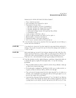
Step 2. Check the Fuse
Step 2. Check the Fuse
1
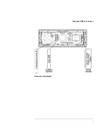
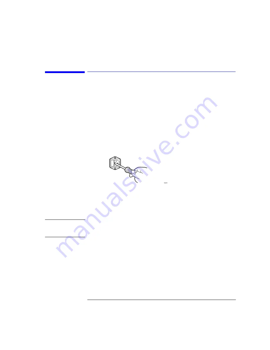
Locate the line-input connector on the instrument’s rear panel.
2
Disconnect the line-power cable if it is connected.
3
Use a small flat-blade screwdriver to open the pull-out fuse drawer.
4
Verify that the value of the line-voltage fuse in the pull-out drawer is correct.
The recommended fuse is an IEC 127 5
×
20 mm, 6.3A, 250 V, Agilent part
number 2110-0703.
Notice that an extra fuse is provided in a drawer located on the fuse holder.
W A R N I N G
For continued protection against fire hazard, replace line fuse only
with same type and ratings, (type T 6.3A/250V for 100/240V
operation). The use of other fuses or materials is prohibited.
Содержание 83437A
Страница 1: ...Agilent 83438A Erbium ASE Source User s Guide ...
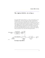
Страница 5: ...v The Agilent 83438A At a Glance Rear view of instrument ...
Страница 8: ......
Страница 10: ......
Страница 24: ...2 4 Making Measurements Performing Stimulus Response Measurements ...
Страница 41: ...3 Specifications 3 3 Regulatory Information 3 6 Specifications and Regulatory Information ...
Страница 47: ...3 7 Specifications and Regulatory Information Regulatory Information Declaration of Conformity I ll ...
Страница 48: ......
Страница 54: ......
Страница 61: ...5 7 Servicing General Information ...
Страница 63: ...5 9 Servicing General Information ...
Страница 79: ...5 25 Servicing Adjustment Procedure ...
Страница 85: ...5 31 Servicing Replacing Instrument Assemblies Location of resistors R2 R8 and R9 ...
Страница 92: ...5 38 Servicing Replaceable Parts ...
Страница 94: ...5 40 Servicing Replaceable Parts ...
Страница 96: ...5 42 Servicing Replaceable Parts ...
Страница 98: ...5 44 Servicing Replaceable Parts ...
Страница 100: ...5 46 Servicing Replaceable Parts ...
Страница 106: ......