Agatec A510S Скачать руководство пользователя страница 24

45

GB F E D I N FIN NL 

44

2.

Mettre le laser en marche et attendre que le laser se cale.  

3.

Passer en mode scanning.

4.

Déplacer le scanning manuellement le long du fil à plomb.

Si le plan n’est pas parfaitement parallèle au fil à plomb, l’axe
Z doit être calibré. 

4.2.2 Calibrage de l’axe Z

1.

Eteindre l’appareil. 

2.

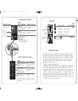
Mettre le A510S en mode vertical. Tout en maintenant

appuyé la touche Man (19), allumer l’appareil (17).

3.

Après quelques secondes, relâchez la touche Marche/Arrêt.

4.

Lorsque le signal lumineux (20) est allumé, relâcher la touche Man.

5.

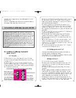
Appuyer sur la touche (19) pour changer l’axe de calibrage. 

Le signal lumineux situé à proximité de l’indication Z (22) 
clignotera pour vous informer que votre A510S est prêt à être 
calibré sur l’axe Z. 

6.

Déplacer le plan laser en utilisant les touches (< 13 ou >14)

de manière à ce que le plan soit parfaitement parallèle au fil à
plomb.

7.

Déplacer le point laser le long du fil à plomb manuellement

ou à  de manière à procéder au contrôle final.

8.

Appuyer sur la touche 

-

ou • (15) afin de sauvegarder les

données ou appuyer sur la touche Marche/Arrêt si vous pensez
avoir fait une erreur. 

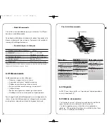
4.3 Contrôle d’erreur conique

1.

Positionner votre A510S à 1 mètre d’un mur (a) ou d’une mire

et à 30 mètres d’un autre mur (b) ou d’une autre mire.

2.

Mettre le laser en marche.

3.

Lorsque le laser est calé, stopper la rotation de la tête en

appuyant sur la touche 15  jusqu’à l’arrêt de la tête.

4.

Marquer alors la position du centre du rayon sur le mur proche (a)

manuellement ou en utilisant un détecteur si les conditions ambiantes de
luminosité vous empêche de voir parfaitement le point. 

5.

Marquer également la position du centre du rayon sur le mur le

plus éloigné (b’), en utilisant un détecteur si nécessaire.  

6.

Installer le A510S à 1 mètre du mur (b’) Lorsque le A510S est

calé, pointer le point laser sur la marque précédente (b). 

GB F E D I N FIN NL 

Important :

Une pression sur la touche du clavier est équiva-

lente à un réglage de 1mm à 100 mètres. 

6.

Si l’axe Y ne doit pas être calibré, vous pouvez sauvegarder

les données en appuyant sur la touche 

-

ou • (15) du clavier. 

Si vous pensez avoir fait une erreur lors de la calibration, vous
pouvez sortir du mode calibration et revenir à la calibration
précédente en appuyant simplement sur la touche Marche /Arrêt.  

Si l’axe Y doit être calibré, vous pouvez changer l’axe de cali-
bration en appuyant sur la touche 

+

ou 

>>I

(16). Le signal

lumineux placé à proximité de la touche H.I. (21) clignotera pour
vous informer que votre laser est prêt à être calibré sur l’axe Y. 

Calibration de l’axe Y 

1.

Assurez-vous que le signal lumineux situé à proximité de la

touche H.I. clignote. Si non : 

• Tout en maintenant appuyé la touche Man (19), allumer

l’appareil (17). 

• Après quelques secondes, relâchez la touche Marche/Arrêt.
• Lorsque la LED (20) est allumé, relacher la touche Man. 

Le signal lumineux (20) clignotera rapidement puis lentement pour
vous indiquer que vous êtes en mode calibrage. 

• Appuyer sur la touche 

+

ou 

>>I

(16) pour changer l’axe de

calibrage.  Le signal lumineux (21) clignotera alors pour vous
informer que vous pouvez calibrer l’axe Y.

2.

Faites pivoter votre laser de telle manière à ce que l’axe Y

soit face au mur (où vous avez marqué le point de calibrage Y).  

3. 

Attendez que le A510S soit calé. 

4.

Appuyer sur la touche < (13) pour monter le point ou sur la

touche > (14) pour baisser le point jusqu’à arriver au point de 
calibrage Y. 

5.

Pour sauvegarder les données, appuyer sur la touche

-

ou • (15).

If you need a rotating beam for the detector, press the scan key.

6.

Si vous pensez avoir fait une erreur lors de la calibrage de

l’axe Y, vous pouvez sortir du mode calibrage et revenir à la 
calibrage précédente en appuyant sur la touche Marche /Arrêt.  

4.2 Contrôle et calibrage vertical (axe Z) 

4.2.1 Contrôle vertical 

1.

Placer le A510S en mode vertical sur une surface plate à

environ 6 mètres d’un fil à plomb courant le long d’un mur. 

A510S-dec2007  10/12/07  19:58  Page 44

Содержание A510S

Страница 1: ...Automatic Laser...

Страница 2: ...ease with Stop rotation Press and hold until it stops Chalk line Flip collar on head up for chalk line down for point Move stationary point or chalk line left Press Move stationary point or chalk line...

Страница 3: ...self leveling in both horizontal and vertical modes Motorized mount speeds setup for ceilings and partitions Manual leveling in X and Y axes for dual slope setting 10 Semi automatic single axis slope...

Страница 4: ...14 16 13 15 17 20 19 18 21 22 2 1 4 3 12 12 10 6 9 8 11 5 7 A510S dec2007 10 12 07 19 58 Page 145...

Страница 5: ...6 1 4 Laser overview See inside front cover for photos of the laser and keypad corre sponding to these callouts See separate descriptions of motorized mount remote control and detectors 1 Rotating hea...

Страница 6: ...the scan functions 4 To move the scan to the left hold the key To move to the right use the key 13 and 14 5 To stop scanning again press simultaneously on the and keys 15 and 13 8 2 2 Automatic Manual...

Страница 7: ...on t raise or lower the wall mount for 5 minutes the laser will go back to its previous mode You ll hear a 4 second beep 2 7 3 Using the motorized mount and laser on the floor 1 Check that the laser a...

Страница 8: ...return to automatic mode IMPORTANT In manual mode the head will rotate even if the laser is not leveled The H I Alert func tion is not available when your laser is in manual mode 12 2 Flip down the su...

Страница 9: ...A510S 14 2 9 3 Inclined plane The laser can also be tilted for manual slope at various angles on the wall mount A tripod with rotating mounting plate will speed setup 1 Set the laser in vertical mode...

Страница 10: ...alibrated in X axis 5 If you have not moved the laser use the X marks made in previous steps of Checking X axis If you need a rotating beam for the detector press the scan key 6 Use the arrow keys to...

Страница 11: ...d to bring the rotating Z beam paral lel to the plumb line 18 7 After completing the X calibration press the or I key 16 to change the axis and to calibrate the Y axis When the Y LED blinks slowly the...

Страница 12: ...ess the MAN key 19 to change to Z axis The Z LED 22 will blink rapidly for a bit and then slowly indicating it s ready to be calibrated in Z axis The beam will not be rotating When it s in calibration...

Страница 13: ...screen front On grade alignment notch Detection window Magnet Window for remote s infrared signal Level vial 6 Accessories LCD screen rear Bubble vial to plumb rod 9V battery compartment follow polari...

Страница 14: ...te control mode If in detection mode press On Off to change to the remote control functions If the detector is not on press any key except the On Off to use it as a remote control for the laser 25 24...

Страница 15: ...by Customer s or any other person s misuse neg lect improper installation unauthorized attempts to open repair or modify the Product inadequate maintenance disre gard of operating instructions excessi...

Страница 16: ...repair or refund of the purchase price paid at the manufactur er s option This limitation of liability for damages will not be affected if any remedy provided herein shall fail of its essential purpo...

Страница 17: ...angle scanning sur l A510S appuyer sur quand le laser est en mode scanning sur la TL25 appuyer sur Diminuer l angle de scanning sur l A510S appuyer sur quand le laser est en mode scanning sur la TL25...

Страница 18: ...oit D placement scanning droit Descendre le point 15 R duire la vitesse de rotation Diminuer angle de scanning 32 Bien que le A510S soit tr s simple d utilisation nous vous recommandons vivement de li...

Страница 19: ...yon laser si l altitude du laser change ou si l appareil est bouscul L arr t de la rotation sera coupl la mise en fonc tion d une alarme sonore Attention La fonction Tilt n est disponible qu en mode a...

Страница 20: ...er la ligne laser ralentir jusqu l obtention du point laser 15 puis faire basculer le levier situ sur la t te de l ap pareil 5 Il est possible de d placer la ligne vers la gauche ou la droite en bouge...

Страница 21: ...D ployer le pied situ sur la plaque ajustable du support mural 3 Ajuster la vis situ e sur ce pied afin de stabiliser le laser sur le sol 4 Appuyer sur la touche scanning de la t l commande plusieurs...

Страница 22: ...heures 3 Alimentation D marrer la rotation de la t te en maintenant enfonc la touche 16 pendant 2 secondes Il est tr s important de v rifier que votre laser n a pas boug et que vos mesures sont toujo...

Страница 23: ...pr t tre calibrer sur l axe X If you need a rotating beam for the detector press the scan key 5 Appuyer sur le touche 13 pour monter le point ou sur la touche 14 pour descendre le point jusqu atteind...

Страница 24: ...ant Une pression sur la touche du clavier est quiva lente un r glage de 1mm 100 m tres 6 Si l axe Y ne doit pas tre calibr vous pouvez sauvegarder les donn es en appuyant sur la touche ou 15 du clavie...

Страница 25: ...ter l appareil et ses accessoires dans le coffret de transport 2 Bien que votre A510S soit r sistant la pluie et la poussi re vous devez le conserver ainsi que ses accessoires secs et propres Nous vou...

Страница 26: ...le appara t sur l cran cela signifie que la cellule est au niveau du rayon laser 5 Presser la touche On Off pour teindre la cellule Elle s teindra automatiquement apr s 10 minutes de non utilisation u...

Страница 27: ...66 Dimensions 15 x 8 x 3 5 cm 2 kg D pend du laser utilis La pr cision varie en fonction du diam tre du rayon et de la distance jusqu au laser 6 2 T l commande La t l commande pourra tre utilis e pour...

Страница 28: ...elle ci soit li e un contrat un quasi contrat ou un d lit n gligence incluse pour tout dommage 53 52 7 Garantie fabricant internationale Replace Le fabricant with the French word for the manufacturer...

Страница 29: ...dans le cas o Le fabricant ou les reven deurs autoris s ont t inform s de la survenance possible de tels dommages RESTRICTION Si un tribunal n accepte pas l enti re exclusion ou la limitation des gar...

Страница 30: ...arriba para la linea abajo para el punto Mover el punto o la presionar la tecla Linea a la izquierda Mover el punto o la presionar la tecla Linea a la derecha Scanning presionar simult neamente las t...

Страница 31: ...ontal 11 5 8 montaje tr pode modo vertical 12 Sensores para la se al del control remoto 1 1 Descripci n El A510S es un l ser visible autom tico que puede ser usado para nivelaci n alineaci n vertical...

Страница 32: ...ece a girar la luz brillara mas despacio indicado que la H I Alerta est activada Si el l ser es manipulado mientras H I Alerta est activado la cabeza se parar el rayo l ser dejar de emitir la luz indi...

Страница 33: ...evo Chequee si la ele vaci n del rayo ha sido cambiada de la posici n original El l ser no permanece en H I Modo alerta presionar tilt 18 para volver al modo H I Alerta Esta funci n es solo posible en...

Страница 34: ...cionar el plano de rotaci n perpendicular una l nea de referencia Como mover el soporte manualmente uso 6 Precauci n tenga cuidado cuando usted este en el modo de soporte no presione las teclas o a me...

Страница 35: ...a arriba de la base ajustable que est encima de su punto de referencia 2 Despu s de que el l ser se ha autonivelado pare la rotaci n de la cabeza 3 Mantenga la tecla scan apretada varios segundos y po...

Страница 36: ...mente Y X X Y 2 Use un destornillador para quitar la tapa del compartimiento de las bater as 3 Inserte dos bater as alcalinas tipo LR20 siguiendo la polari dad indicada en el compartimiento de las bat...

Страница 37: ...Y 4 Marque la localizaci n del centro del rayo cerca de la primera marca 5 Sobre 30 metros las marcas no deber an tener una diferen cia de mas o menos 6 mm Esto esta dentro de su precision 6 Si las m...

Страница 38: ...a calibraci n de la Z presione las techas o y gu rdelo El l ser saldra a Off Si usted no est seguro de la calibraci n y no desea guardarla ponga el l ser en off con la tecla On Off Proceda a chequeo f...

Страница 39: ...s de utilizarlos limpi ndolos de polvo etc No guarde el l ser en temperaturas de 20 o 90 porque algunos complementos electr nicos puede ser da ados No guarde el l ser en la caja en caso de que se haya...

Страница 40: ...normal S lido Volumen alto Sin bocina Silencio Grueso Fino Bajo Nivel no alcanzado Nivel ptimo Nivel excedido Alto ESATDO DE LA BATER A PRECISI N Pantalla LCD Modo detecci n 1 Pulse el bot n de encend...

Страница 41: ...ando a distancia permite detener comenzar o variar el senti do de rotaci n del haz de l ser as como mover el haz vertical a izquierda y derecha Tambi n sirve para controlar la exploraci n y la calibra...

Страница 42: ...ente el incumplimiento de las instrucciones de servicio inten tos inautorizados de abrir reparar o modificar el producto por parte del cliente o cualquier tercera persona excesos de carga o de uso el...

Страница 43: ...to el uso las prestaciones la aver a permanente o temporal del pro ducto o en conexi n con estos casos limitando su responsabili dad a su albedr o al reemplazo la reparaci n o el reembolso del precio...

Отзывы: