background image


Page 34 

AGA Ludlow Electric Standard Stove 
Installation & User Manual 


With AGA Rangem

aster’s Policy of Continuous Product Improvement, the Company reserves 

the right to change specifications and make modifications to the appliance described and 

illustrated at any time 


AGA 

Rangemaster 

Station Road, Ketley 

Telford, Shropshire 

TF1 5AQ 

United Kingdom 

www.agastoves.co.uk 


This Stove has been fully CE Tested, Approved 

& Manufactured in the UK 


This stove conforms to all relevant European Directives 


Содержание Ludlow

Страница 1: ...NSTALLER LEAVE THIS MANUAL WITH THE APPLIANCE CUSTOMER PLEASE RETAIN THIS MANUAL FOR FUTURE REFERENCE For use in GB IE United Kingdom and Ireland Document No RH ELEC LUD AS AM Iss 02 01 2020 File Ludlow Electric ECE AS Standard_User_Man doc ...

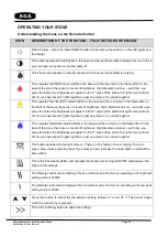
Страница 2: ...A NON COMBUSTIBLE HEARTH 10 UNPACKING AND TESTING APPLIANCE 12 WHAT COMES WITH THE STOVE 13 FITTING THE REAR WALL FIXING BRACKET 14 SETTING UP THE LOG SET MEDIA 17 LOG SET SAMPLE LAYOUT 18 OPERATING YOUR STOVE UNDERSTANDING THE ICONS 20 MANUALLY OPERATING THE STOVE INSTRUCTIONS 22 REMOTE CONTROL OPERATION INSTRUCTIONS 23 STOVE RESET SEQUENCE 27 CARE AND MAINTENANCE 27 EXPLODED VIEW PARTS LISTS 29 ...

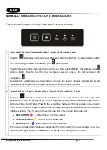
Страница 3: ...e Contact Number 5 What is the serial Number of your stove This can we found inside the front door above the bottom hinge Serial Number 6 What date was your stove Installed Installation Date 7 The AGA Name Model Type reference for this stove is Name Ludlow Standard Model LUD ELEC A5S Type Electric Technical Data Summary Reference Description Data 1 Maximum Heat Output 1 9 kW Equivalent to approx 6...

Страница 4: ...n given supervision and or instruction concerning use of the appliance in a safe way and understand the hazards involved However if you do not deem the child or person competent only allow them to operate the stove when a competent adult is in the room to supervise 7 CHILDREN OF LESS THAN 8 YEARS SHOULD BE KEPT AWAY UNLESS CONTINUOUSLY SUPERVISED BY A COMPETENT ADULT If you are installing your app...

Страница 5: ...me in contact with water moisture or Steam i e Kitchen Bathroom or Wet Room Never use aerosols or steam cleaners near this product Never route the electric cable near the heater outlet Never route the electric cable under carpets or floor coverings Never install this product close to curtains or any combustible materials Never use the heater to dry clothes or other objects Never remove the stove f...

Страница 6: ...Test Certificate Manufacturer AGA Rangemaster Product Name Model Ludlow Standard Electric Stove LUD ELEC A5S Description Room heater Certificate Number C 19 4649B Test Standards EN 60335 2 30 2009 A11 2012 EN 60335 1 2012 A11 2014 A13 2017 Tested at Kiwa Blackwood Compliance Laboratories Blackwood NP12 2DG United Kingdom CONFORMITY WITH DIRECTIVES This stove conforms to all relevant European Direc...

Страница 7: ...ping hazard 12 To disconnect the heater turn the controls to OFF before removing the plug from the outlet 13 Do not insert or allow foreign objects to enter any ventilation or exhaust opening as this may cause an electric shock fire or damage to the heater 14 To prevent a possible fire do not block air intakes in any way 15 A heater has hot and arcing or sparking parts inside Do not use it in area...

Страница 8: ...FF ETC Always install the heater in accordance with this guide If in doubt obtain expert advice Always make sure the electrical socket is accessible and located adjacent to but not above the heater Always disconnect the heater from the electrical supply before moving it or carrying out cleaning maintenance Always make sure the heater is firmly secured to prevent it from being tipped over using the...

Страница 9: ...Page 9 AGA Ludlow Electric Standard Stove Installation User Manual STOVE DIMENSIONS Manual Controls and the ON OFF Switch Front View Right Hand Side View Rear View Top View Drawings are Not to Scale ...

Страница 10: ... This stove must be fitted on to a Non Combustible Hearth with a minimum thickness of 12mm which extends 225mm from the front of the door of the stove Minimum of 100mm from the rear of the stove Minimum of 75mm either side of the stove Hearth Must Extend 225mm to the front of the Stove Hearth Must Extend 100mm to the rear of the Stove Must be Installed onto a Non Combustible 12mm thick Hearth ...

Страница 11: ...l Air Intake Grill shown in white box above this must be kept clear of any foreign objects such as Pet Hairs Carpet Fluff this must be regularly cleaned so the vents are clear of foreign objects such as dust debris fibres Mains Socket Plugs in Here Rear Cool Air Inlet Vent KEEP CLEAR Hot Air Output Vent KEEP CLEAR Must be Installed onto a Non Combustible 12mm thick Hearth Rear Wall Fixing Bracket ...

Страница 12: ...rong open the windows and operate the stove on the full heat setting for 30 to 45 minutes to allow the paint to cure children the elderly or pets should not be allowed into the room during this period WARNING ELECTRIC SHOCK HAZARD It is the customers responsibility to contact a qualified electrical installer to make sure the electrical installation is adequate and in conformance with the regulatio...

Страница 13: ...5 Wall Fixing Bracket please note this is already fitted to the rear of the stove Item 2 Remote Control Item 3 Power Code Item 1 Log Media Pack includes the following 11 x Piece Log set various sizes Large bag of Glass Amber Bead Embers Small bag of White Vermiculite Chippings Small bag of Black Vermiculite Chippings All of the items are packed into this cardboard box In the box is Item 1 Log Medi...

Страница 14: ...evel into the rear wall Step 2 Insert 3 X 30mm Long Brown Rawplugs into the 3 drilled holes in the back wall marked as item 1 FITTING THE REAR WALL FIXING BRACKET This bracket must be fitted to the rear of the stove to ensure that the stove will not tip forward when the stove door is opened 12mm thick Non Combustible Hearth Back Wall which the Stove Bracket will be Mounted onto ...

Страница 15: ...m 3 with 3 x no M5 x 25mm long posi drive screws item 4 as shown Note orientation of the bracket Step 4 Offer up the fire to the wall bracket so the two brackets align fit the 2x no M5 x 20mm long cap screw supplied into bracket adjust distance to wall to suit max 102 5mm min 65mm tighten screws ...

Страница 16: ...d earlier in this manual Please ensure there is 100 mill gap at the rear so COOL air from the room can enter into the rear of the stove without any restriction IMPORTANT Please make sure the front Hot Air outlet and the rear Cool Air inlet are regularly cleaned so no foreign matters such as pet hairs and carpet fluff can block these 2 vents NEVER COVER THIS STOVE THIS COULD CAUSE A FIRE Now just p...

Страница 17: ...TTING UP THE LOG SET MEDIA Your Stove is supplied with 11 piece log Amber Glass beads and Black and White Vermiculite chippings Large Bag of Amber Glass Bead Embers to be placed onto LED light base of the stove Small bag of White and Black Vermiculite chippings to place over the logs and Amber glass beads to enhance the real log burning feature ...

Страница 18: ... with the base lights and the rear flame effect turned on only using the Yellow light option Step 1 Now you are ready to place the media and logs into your stove Firstly pour the bag of amber glass beads onto the glass base plate which will allow the light from the base lights to diffuse and glow ...

Страница 19: ...the black and white vermiculite chippings you can just sprinkle these over the top of the logs for that final log burner effect Now just clean the door glass inside and out with a damp cloth then close the door The door only needs to be reopened if you wish to change the log arrangement So for safety reasons keep the door closed You probably won t want to use all 11 x logs in the fire bed at the s...

Страница 20: ... the button this light colour will turn off You can operate all 3 lights together or just one colour or 2 colours together This operates the BLUE coloured LEDs in the base and the red colour in the flame effect in the back of the stove there are 3 x levels of brightness High Medium and Low each time you press the button the brightness will adjust on the 4th press of the button this light colour wi...

Страница 21: ...de of the stove for Manual Operation Press this button to turn ON OFF and adjust the Fan Heater output HIGH LOW Press this button to turn ON OFF and adjust the brightness of the LED base lights and the rear flame effect N B All 3 light colours operate together only from this button Side Screen on stove light is RED indicates heater is on the High Heat setting of 1900W Side Screen on stove light is...

Страница 22: ...e thermostat sensor which is located inside the stove 2 FLAME EFFECT ONLY BLUE RED YELLOW LED LIGHT OPTIONS Press key button key on the touch pad When pressed for the first time the bottom base LED lights and rear flame will light up on their highest brightness setting this automatically brings on all 3 x light colours Blue Red Yellow Press for the second time the base LED lights and rear flame ar...

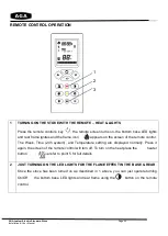
Страница 23: ...screen of the remote control The Week Time 24h system and Temperature setting are displayed normally Press it again the screen of the remote control will turn off To turn on the heat press the heater button please refer to point 5 for full details 2 JUST TURNING ON THE LED LIGHTS FOR THE FLAME EFFECT IN THE BASE REAR Once the stove has been turned on as described in 1 above you can just operate tu...

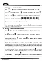
Страница 24: ...on turn off and adjust the top light colors The buzzer beeps once when the key is pressed There are 16 shades of colour varying from red green blue violet purple yellow If you want you can just have the down lights on without the flame effect 5 TURNING ON THE HEATER ONLY HIGH LOW HEAT Press the Heating key When pressed for the first time the heating elements works at the High Heat setting of 1900W...

Страница 25: ...he temperature setting flashes press to set the timing temperature for Monday press key to confirm and then press the time setting for timing The displayed time parameter is 00 23 Press to set the current operating state of timing function indicates that the timing is on currently and the control temperature is the temperature setting indicates that the timing is on currently and the control tempe...

Страница 26: ...screen displays icon the indicator on the stove lights yellow Press again to turn it off the LCD screen does not display icon and the indicator on the stove goes off The buzzer beeps when the key is pressed After the Open Window function is turned on the program firstly detects if the heating function is turned on If it is turned on the program will save the current ambient temperature value and d...

Страница 27: ...ts CAUTION Unplug from the mains electrical supply and allow the product to completely cool before handling or cleaning it 3 Do not allow water or other liquids to run into the interior of the product as this could create a fire and or electrical hazard 4 We also recommend the periodic cleaning of this appliance by lightly running a vacuum cleaner nozzle over the guards to remove any dust or dirt ...

Страница 28: ...rials contained within Your co operation is vital to ensure the success of these schemes and for the protection of the environment REPLACEMENT PARTS FOR THE ELECTRIC FIRE BOX ONLY NO PART NUMBER DESCRIPTION QTY Ludlow ECE Standard Ludlow ECE Wide N A 1 TOP PANEL 1 2 602065D BLOWER AND HEATER ASSEMBLY 1 3 601094F CIRCUIT BOARD 1 4 FIREPLACE BOX 1 5 10104010 SWITCH 1 6 601035 CONTROL PANEL 1 7 30150...

Страница 29: ...ting Bracket 1 10503 5 Wall Mounting Bracket 2 10504 6 EC5 Electric Firebox Assembly 10505 7 Front Ash Lip 10506 8 9 6 M5 X 15 CAP SCREW 10507 10 1 Handle Assembly 10508 11 1 M6 CSK x 30mm Screw Handle Pivot 10509 12 M6 CSK x 25mm Screw 10510 13 A5 Glass Gasket 10511 14 A5 Standard Electric AGA Glass 10512 15 16 17 4 Glass Clips Fixing Screws Washers 10513 18 19 1 Handle Roller and Fixing Screw 10...

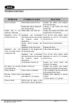
Страница 30: ...t house circuit breaker Appliance s fuse has blown Replace the fuse Appliance will not come on when switch is flipped to ON Appliance is not plugged into an electrical outlet Check plug and plug in Appliance has overheated and safety device has caused the thermal switch to disconnect Turn off the main switch allow appliance to cool for 10 minutes then turn on Circuit board is burnt out Inspect the...

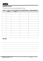
Страница 31: ...A Ludlow Electric Standard Stove Installation User Manual SERVICE HISTORY This heater must be serviced annually depending on usage Date Dealer Name Service Technician Name Service Performed Special Concerns NOTES ...

Страница 32: ...n your dated sales invoice receipt as a proof of purchase During your extended warranty period only genuine spare parts must be used in the servicing and maintenance of your stove these spare parts can be ordered via the Premium Retailer directly Consumable items such as glass paint screens door rope seals bulbs LED light boards ceramic plaster fuel effects remote controls glass beads and batterie...

Страница 33: ...warranty claim because of a product fault or defect you must inform us within a reasonable amount of time this is within 14 days from the date on which the fault or defect first became apparent If the product fault or defect is notified after 14 days from the date on which the fault or defect became apparent we cannot accept any liability for events or issues which arise after the 14 day period or...

Страница 34: ... reserves the right to change specifications and make modifications to the appliance described and illustrated at any time AGA Rangemaster Station Road Ketley Telford Shropshire TF1 5AQ United Kingdom www agastoves co uk This Stove has been fully CE Tested Approved Manufactured in the UK This stove conforms to all relevant European Directives ...
Отзывы: