background image

11

Understanding OTDR Test Parameters

Parameter

Description

Range

The [Range] parameter determines the distance range of the full (unzoomed) trace. It 
also determines the distance between data points in the trace: the longer the range, 
the wider the data point spacing. We recommend selecting the shortest distance 
range that is longer than the fiber under test. For example, to test a fiber that is 
1.5 km long, select the 3 km range.
Available [Range] values: 250 m, 500 m, 1, 1.5, 3, 6, 15, 30, 60, 120, 240 km

Pulse

The OFL280 can operate using different pulse widths. Short pulse widths provide 
the shortest event and attenuation dead zones. Long pulse widths provide the range 
needed to test long fibers.
Available [Pulse] values:  5, 10, 30, 100, 300 ns, 1, 3, 10 µs.

Averaging

The [Averaging] parameter determines the duration of a timed test and the number 
of trace averages performed. The longer the test the smother the trace.
Available [Averaging] values:  5, 10, 15, 30, 60, 90, 180 sec.

Resolution

Available: [Normal] or [High].
Set to [High] to see events that are close together; set to [Normal] for longer range.

Setting Test Parameters

Range

Range should normally be set to a value longer than the known length of the fiber under test. Shorter 
values may be used to obtain a higher resolution trace of the initial portion of the fiber. If you do not 
know the length of the fiber, start with a quick scan using a long range to determine where the fiber 
end is, then re-scan with a more appropriate range setting.

Note:

 The OFL280 automatically determines the appropriate Range setting In Full Auto and FTTx – In 

Service modes.

Содержание OFL280 FlexTester

Страница 1: ...OFL280 FlexTester User Guide www AFLglobal com or 800 321 5298 603 528 7780...

Страница 2: ...L280 103 only 13 FTTx PON Construction Test Mode Settings 14 Full Auto Test Mode Settings 14 Real Time Test Mode Settings 15 Expert Test Mode Settings 15 Event Thresholds FTTx In Service mode 16 Event...

Страница 3: ...rs Using the Save As Page 29 Selecting a Cable as the Current Cable folder 29 Saving Test Results 29 Opening Files Reviewing Saved Results 29 Deleting Jobs Cables Traces 30 Transferring Files to a PC...

Страница 4: ...ce heavy objects on the power cord or expose it to heat Never touch the AC adapter while your hands are wet Should the power cord become seriously damaged internal wiring exposed or shorted contact th...

Страница 5: ...ust mate with the fiber optic link under test Launch and Receive cables are required to measure the insertion loss and reflectance of the near end and far end connectors respectively on the fiber link...

Страница 6: ...and arrow keys depends on which menu or editor submenu is displayed Function of each key is explained in the section titled Using OFL280 Keys Soft function keys Back key Menu key Display Used to show...

Страница 7: ...d laser OTDR OLS port This is a CLASS I LASER output and input for FTTx PON meter OFL280 103 model only OPM port Top Panel Test Ports Side Panel USB and Power Ports Power port This is the interface fo...

Страница 8: ...etup parameters Trace Page in the Zoom mode these keys are used to adjust zoom In the Move mode Left and Right keys are used to move cursors Select A B This key provides several functions Main Menu pr...

Страница 9: ...50 nm OFL280 Setup OTDR Modes Test Mode Network Applications Setup FTTx In Service PON power meter Customer fiber fault location fiber may be live or dark Test live fibers through splitter Auto or Sem...

Страница 10: ...download software upgrades OTDR is connected to a PC Press to display the last OTDR trace viewed Selecting a Test Mode 1 Press the Menu key to display the Main menu The Mode menu page A is displayed b...

Страница 11: ...Available Pulse values 5 10 30 100 300 ns 1 3 10 s Averaging The Averaging parameter determines the duration of a timed test and the number of trace averages performed The longer the test the smother...

Страница 12: ...long fiber the trace may reach the noise floor before the end of the fiber is reached Averaging Longer averaging times improve dynamic range and can be used to compensate for some of the range lost wh...

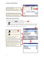
Страница 13: ...03 only In the FTTx In Service mode available only in the OFL280 103 model the first page displays received FTTx PON power at 1490 and 1550 nm On dark fibers users can test at 1310 1550 nm On live fib...

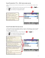
Страница 14: ...sired test setup parameter to set Use keys to set change the highlighted parameter Use keys to set the Range parameter to a value that is greater than the longest end to end distance in the PON from c...

Страница 15: ...eter to Off or By Range Off Setting the Auto Setup parameter to Off allows the user to set the Range Pulse and Resolution parameters By Range Setting the Auto Setup option to By Range allows the user...

Страница 16: ...er 3 Use keys to set change the highlighted parameter Note Event Loss and Reflectance threshold settings are used to determine whether or not a detected anomaly should be reported as an event and incl...

Страница 17: ...splay the Event menu A using keys 2 Use keys to highlight the desired setup parameter 3 Use keys to set change the highlighted parameter This parameter may be set to PON Default OFL 280 sets Event Los...

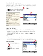
Страница 18: ...Use keys to highlight the desired parameter to set 3 Use keys to change the highlighted parameter Event Thresholds Expert mode In Expert mode the Events parameter may be set to Auto or Off When set t...

Страница 19: ...enu use keys to display the Cables menu page A 2 Use keys to highlight the desired setup parameter 3 Use keys to set change the highlighted parameter This parameter may be set to None Default 1 150 m...

Страница 20: ...will return to dB mode 2 To set a new OPM reference level hold the Ref Set key until you see REFERENCE SAVED This takes about one second 3 When you release the Ref Set soft key the unit should displa...

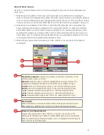
Страница 21: ...ID is detected the user may not change the wavelength value Wave ID Mode Feature Wave ID is a powerful feature which cuts multi wavelength testing time in half and eliminates user setup errors 1 When...

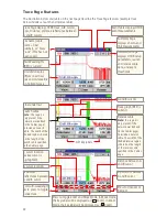
Страница 22: ...Receive cable Note this region is only present if the network was defined in the Cables page to include a Receive cable The width of the shaded receive region is based on the length of the receive cab...

Страница 23: ...itter or sharp bend in the fiber Gainer An event with negative loss which can occur in OTDR traces where two fibers with very different backscatter coefficients are spliced or connected Normally a gai...

Страница 24: ...ht the desired setup parameter Use keys to change the highlighted setup parameter except Event Thresholds parameter You may change these parameters to correct locations in the Event Table after the te...

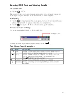
Страница 25: ...he setup menu How can I tell if a test is running The OFL280 Page header will display the Test in Progress icon Test in Progress icon To display the desired Page for viewing use Left and Right Tab key...

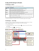
Страница 26: ...ost recently opened recalled from memory To display File Manager press the Files soft key on the Main Menu page or when it appears File Manager Jobs Page Depending on the prior settings the File Manag...

Страница 27: ...ight the symbol at the top of the Traces page and then press Select to display the Cables page Available memory Select to return to Jobs page Press to delete the highlighted Cable folder Press to open...

Страница 28: ...yed use keys to highlight any character position within the Job End1 End2 Cable name fields and Fiber number field 3 Use keys to change the highlighted character 4 Use the keys to select the previous...

Страница 29: ...e highlighted cable current Saving Test Results Test results are stored on the OFL280 Internal Drive Results are saved as industry standard SOR files which can be viewed printed and analyzed on a PC u...

Страница 30: ...S and SOFTWARE 5 Copy the RESULTS folder to your PC 6 Under RESULTS you will see TRACES 7 Under TRACES you will see all of the folders containing traces Note Before removing the USB cable connecting y...

Страница 31: ...on FCC2 to fill the well Dip a CCT stick into the well of the FCC2 to dampen the tip with optical cleaning fluid Place the damp tip over the ferrule to be cleaned Rotate the tip clockwise 10 revolutio...

Страница 32: ...a standard wall outlet Connect the AC adapter charger to the Power port located on the OFL280 side panel The AC Charger indicator on the side panel will turn on Red Charge batteries until the AC Char...

Страница 33: ...NOYES products with or without annual calibration included Any product that is found defective within the warranty period will at the discretion of AFL be repaired or replaced Warranty will be voided...

Страница 34: ...34 Thank you for choosing NOYES Test and Inspection CERTIFIED 9001 ISO NOYES FIBER SYSTEMS www AFLglobal com or 800 321 5298 603 528 7780...

Отзывы: